Heat exchanger

A technology of heat exchanger and heat exchange network, applied in the direction of heat exchanger type, indirect heat exchanger, lighting and heating equipment, etc., can solve the problem of low heat exchange efficiency, increase the contact heat exchange area, slow down the turbulence , the effect of improving heat exchange efficiency

Pending Publication Date: 2018-10-12
GUANGZHOU MARITIME INST
View PDF11 Cites 0 Cited by
  • Summary
  • Abstract
  • Description
  • Claims
  • Application Information

AI Technical Summary

Problems solved by technology

[0006] In order to overcome the technical problem of low heat exchange efficiency in existing heat exchangers, the present invention provides a new

Method used


Image

  • Heat exchanger
  • Heat exchanger
  • Heat exchanger

Examples


Embodiment Construction

[0023] The specific implementation manners of the present invention will be further described in detail below in conjunction with the accompanying drawings and embodiments. The following examples are used to illustrate the present invention, but are not intended to limit the scope of the present invention.

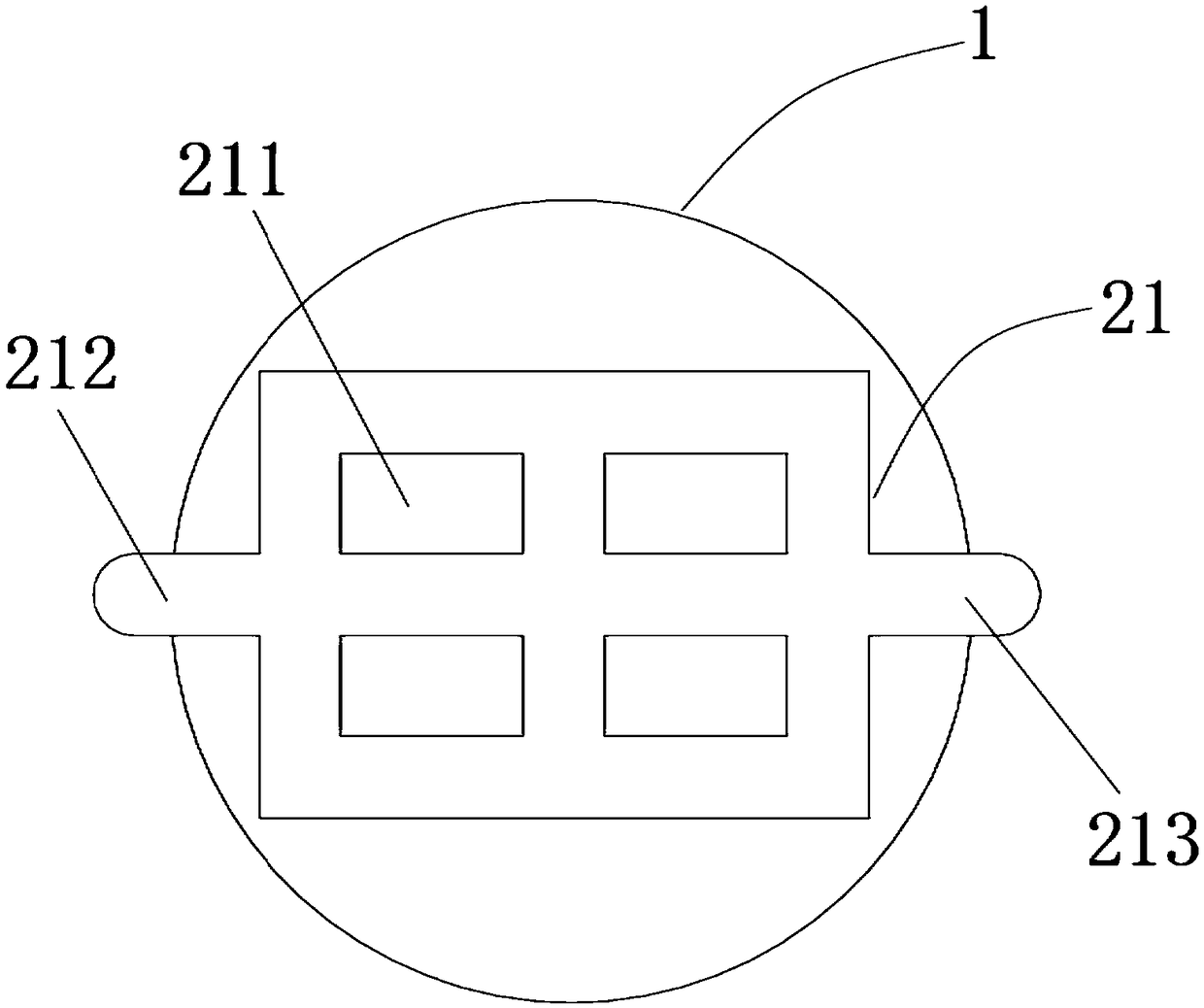
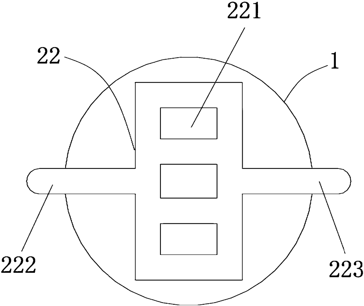
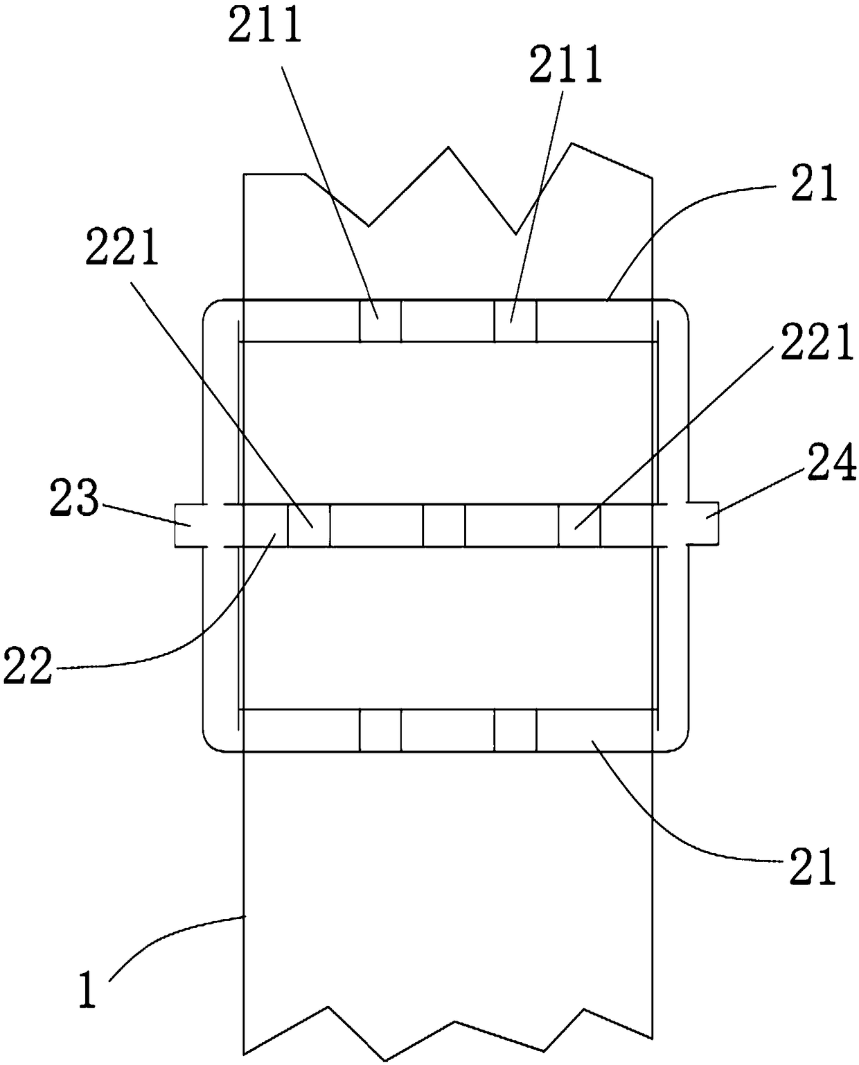
[0024] combine Figure 1 to Figure 5 As shown, a heat exchanger provided by the present invention includes a flow pipe 1 for passing low-temperature fluid, and a mesh pipe 2 arranged in the flow pipe 1 for passing high-temperature fluid;

[0025] The mesh pipe 2 includes a first heat exchange network pipe 21 and a second heat exchange network pipe 22 arranged side by side and communicating with each other; the first mesh hole 211 and the second heat exchange network pipe on the first heat exchange network pipe 21 for allowing low-temperature fluid to pass through The second mesh holes 221 on the 22 for allowing the cryogenic fluid to pass through are arranged in a stagger...


PUM


Abstract

The invention discloses a heat exchanger. The heat exchanger comprises a circulating pipeline for allowing low-temperature fluid to pass through and a mesh-shaped pipeline which is arranged in the circulating pipeline for allowing high-temperature fluid to pass through; the mesh-shaped pipeline comprises a first heat exchange mesh pipe and a second heat exchange mesh tube which are arranged in parallel and communicate with each other; first mesh holes for allowing the low-temperature fluid to pass through in the first heat exchange mesh tube and second mesh holes for allowing the low-temperature fluid to pass through in the second heat exchange mesh tube are alternatively formed; and the mesh-shaped pipeline comprises an inlet for allowing low-temperature fluid to flow into the first heatexchange mesh tube and the second heat exchange mesh tube, and an outlet for enabling heat-exchanged low-temperature fluid to flow out from the first heat exchange mesh tube and the second heat exchange mesh tube. The heat exchanger disclosed by the invention can provide resistance for low-temperature fluid which flows through from the circulating pipeline, has effects of reducing flow speed and disturbing flow for low-temperature fluid, increases a contact heat-exchange area between low-temperature fluid and high-temperature fluid; and moreover, flow of high-temperature fluid is increased, sothat heat exchange efficiency of the heat exchanger is finally improved.

Description


Claims


Application Information

Patent Timeline
Owner GUANGZHOU MARITIME INST
Why Eureka
Try Eureka