
Unmanned-aerial-vehicle-mounted laser dazzling device

A drone and laser technology, applied in the field of drone light source, can solve the problems of increasing power consumption, increasing the weight of mounted equipment, and the effect of optical warning is not obvious, so as to reduce weight and power consumption, and improve concentrated beam Function, the effect of increasing flight time and flight altitude

Active Publication Date: 2018-10-12
陕西艾利克斯光电科技有限公司
View PDF6 Cites 1 Cited by
  • Summary
  • Abstract
  • Description
  • Claims
  • Application Information

AI Technical Summary

Problems solved by technology

However, due to the scattered beams of LED lights and halogen lights mounted on traditional drones, the effect of optical warnings is not obvious. In order to deter offenders, the power must be increased to achieve a certain lighting brightness. The heat will be large, and it is necessary to increase the radiator, which will increase the weight of the entire mounted device and increase the power consumption. The UAVs for this purpose are basically powered by lithium batteries, and their battery capacity is certain. The weight of the camera and the gimbal in the mounting equipment of the drone is basically fixed, so in order to maximize the flight time and flight height of the drone, it is required that the weight of the entire mounted equipment is lighter and the power consumption is smaller. it is good

Method used


Image

  • Unmanned-aerial-vehicle-mounted laser dazzling device
  • Unmanned-aerial-vehicle-mounted laser dazzling device
  • Unmanned-aerial-vehicle-mounted laser dazzling device

Examples


Embodiment Construction

[0059] The following will clearly and completely describe the technical solutions in the embodiments of the present invention with reference to the accompanying drawings in the embodiments of the present invention. Obviously, the described embodiments are only some, not all, embodiments of the present invention. Based on the embodiments of the present invention, all other embodiments obtained by persons of ordinary skill in the art without making creative efforts belong to the protection scope of the present invention.

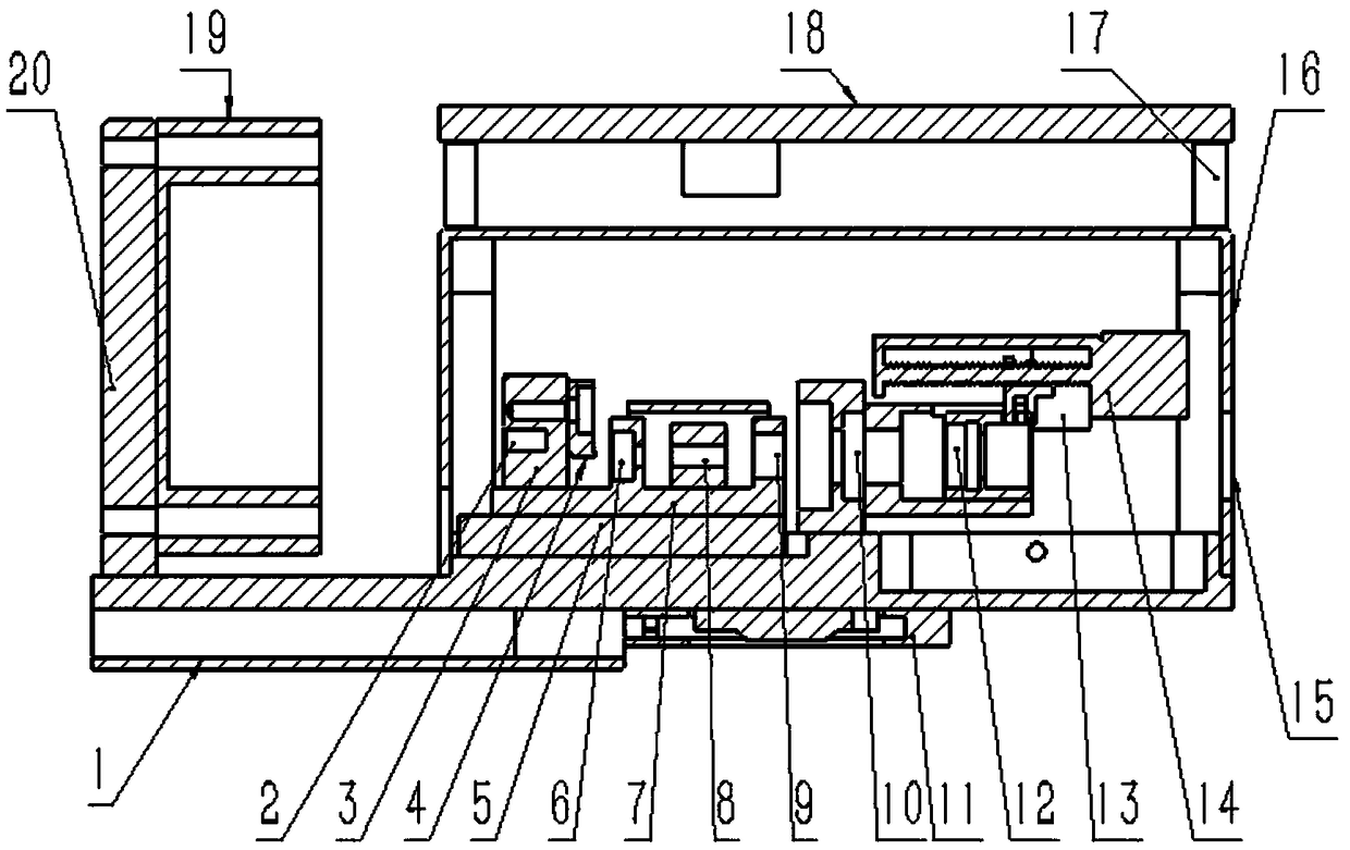
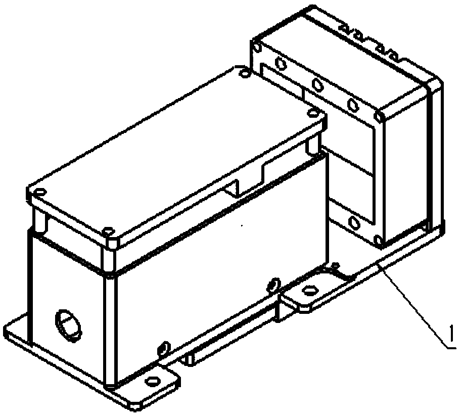
[0060] The object of the present invention is to provide a laser dazzler mounted on an unmanned aerial vehicle, so as to realize concentrated light beams, reduce power consumption and reduce the mounted weight.

[0061] In order to make the above objects, features and advantages of the present invention more comprehensible, the present invention will be further described in detail below in conjunction with the accompanying drawings and specific embodiments.

...


PUM


Abstract

The invention discloses an unmanned-aerial-vehicle-mounted laser dazzling device. The device comprises a dazzling device shell, a heat transfer plate, a signal receiver, a light-emitting assembly, a laser control assembly, a divergent lens, a convergence lens and an electric zoom set; when the signal receiver receives a no-target object, the laser dazzling device is used for lighting, 532nmn continuous light spots are generated, according to the received light spot size signal, the electric zoom set is controlled to adjust the distance between the divergent lens and the convergence lens, and the light spots irradiated to the target are magnified; when the signal receiver receives the target object, the laser dazzling device is used for warning and repelling illegal workers, and 532 nm stroboscopic light spots are generated; according to the received light spot size signal, the electric zoom assembly is controlled to adjust the distance between the divergent lens and the convergence lens, and the light spots irradiated to the target shrink. The dazzling device is adopted, the effect of beam concentrating is improved, the weight and the power consumption of a mounting device are reduced, the flying time of a small unmanned aerial vehicle is prolonged, and the flying height of the small unmanned aerial vehicle is increased.

Description

technical field [0001] The invention relates to the technical field of unmanned aerial vehicle light sources, in particular to a laser dazzler mounted on an unmanned aerial vehicle. Background technique [0002] The use of drones for day or night security patrols in wildlife sanctuaries can save a lot of manpower and material resources. Once the UAV finds someone poaching or cutting down trees in the animal and plant protection area during the patrol process, it needs to be stopped in time. While traditional UAVs discover these illegal acts, they can effectively stop poaching and illegal logging through UAV-mounted broadcasts and LED lights or halogen lights for sound and optical warnings. However, due to the scattered beams of LED lights and halogen lights mounted on traditional drones, the effect of optical warnings is not obvious. In order to deter offenders, the power must be increased to achieve a certain lighting brightness. The heat will be large, and it is necessar...

Claims


Application Information

Patent Timeline
Patent Type & Authority Applications(China)
IPC IPC(8): F41H13/00
CPCF41H13/0056
Inventor 于晓龙艾喜红许刚刚
Owner 陕西艾利克斯光电科技有限公司
Learn More