A high-precision digital array multi-channel delay compensation method

A technology of digital array and delay compensation, applied in the field of digital array, can solve the problem of random delay compensation method without high precision

Active Publication Date: 2019-12-31
GUANGZHOU UNIVERSITY
View PDF7 Cites 0 Cited by
  • Summary
  • Abstract
  • Description
  • Claims
  • Application Information

AI Technical Summary

Problems solved by technology

However, for the random delay caused by RF path differences, filter group delay differences, etc., the consistency difference is generally reduced by improving the channel path consistency design requirements and increasing the component group delay consistency requirements, and There is no high-precision random delay compensation method

Method used


Image

  • A high-precision digital array multi-channel delay compensation method
  • A high-precision digital array multi-channel delay compensation method
  • A high-precision digital array multi-channel delay compensation method

Examples


Embodiment 1

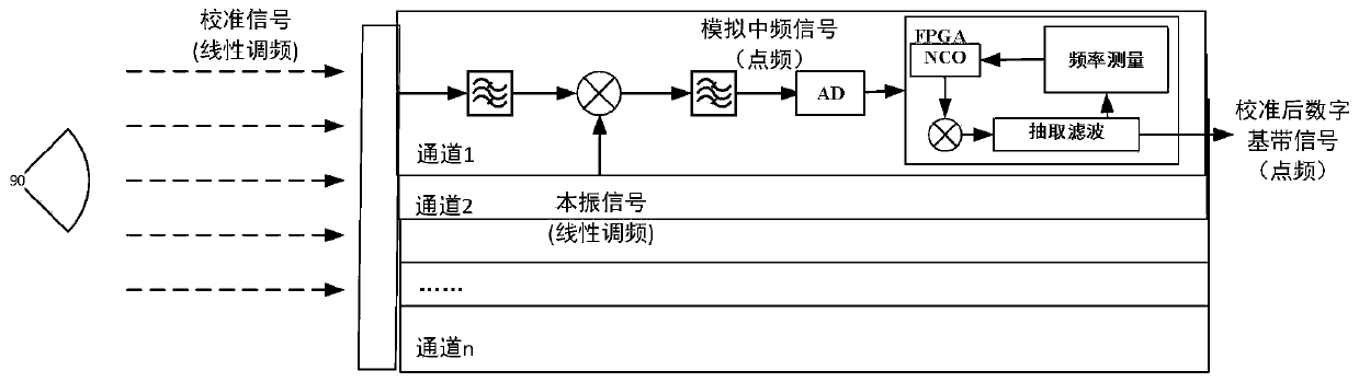
[0090] Embodiment 1 of the present invention provides a high-precision digital array multi-channel delay compensation method, figure 1 A hardware block diagram of a high-precision digital array multi-channel delay compensation method provided by an embodiment of the present invention, the method includes the following steps:

[0091] Step 1. The radio frequency source generates a calibration signal. The calibration signal is a chirp signal with a bandwidth of B and a signal time width of T. After the calibration signal is delayed, the expression of the signal arriving at the entrance of the mixer is:

[0092] S d (t)=Acos[ω 0 (t-t d )+0.5k(t-t d ) 2 ) (1)

[0093]In the formula, t d - channel delay, A - signal amplitude, ω 0 -carrier frequency, T-signal duration, k-FM slope, when the signal bandwidth is B, k=2πB / T;

[0094] Among them, -0.5T+t d ≤t≤0.5T+t d ;

[0095] Step 2. The calibration signal reaches the radio frequency receiving end of each channel of the dig...


PUM


Abstract

The invention provides a high-precision digital array multi-channel delay compensation method, and belongs to the technical field of digital arrays. The method comprises the following steps: generating a calibration signal by a radio frequency source; making the calibration signal arrive at radio frequency receiving ends of all channels of a digital array through space radiation, and mixing and filtering the calibration signal and a local oscillation signal after low-noise amplification and filtering to obtain an analog intermediate frequency signal; converting the analog intermediate frequency signal into a digital signal through AD sampling, and transmitting the digital signal to a frequency measuring device for processing; measuring the frequency of the digital signal in the frequency measuring device to obtain a high-precision frequency value, and calculating the high-precision delay values of the channels through the high-precision frequency value; and changing the NCO (Numerically Controlled Oscillator) frequency value in digital down-conversion of the channels in the frequency measuring device with the delay values as references, and performing frequency compensation equivalence on all the channels to realize delay compensation. Through adoption of the method, hardware of the digital array is not added; the aims of delay measurement and compensation are fulfilled by means of software on the basis of original hardware of an FPGA (Field Programmable Gate Array); and high delay compensation precision and high speed are achieved.

Description

technical field [0001] The invention belongs to the technical field of digital arrays, and in particular relates to a high-precision digital array multi-channel delay compensation method. Background technique [0002] With the continuous development of science and technology, digital array technology has been widely used in radar, communication and other radio technology fields. Digital array technology uses multi-channel spatial beamforming technology, which can obtain high gain, strong directivity, and strong anti-interference performance. [0003] When a digital array is used for broadband signal transmission, it will face the problem of delay compensation. There are two main purposes of the delay compensation, one is to solve the problem of the larger aperture; the other is to solve the problem of inconsistent delay between multiple channels. The problem of greater aperture is caused by the fixed delay of the signal arriving at different positions of the antenna, and t...

Claims


Application Information

Patent Timeline
Patent Type & Authority Patents(China)
IPC IPC(8): H04J3/06H04L27/14H04L27/144H04L27/148
CPCH04J3/0682H04L27/14H04L27/144H04L27/148
Inventor 浣沙戴淦锷
Owner GUANGZHOU UNIVERSITY
Why Eureka
Try Eureka