

Filament current control method and device
A filament current and control method technology, which is applied in the field of medical equipment, can solve the problems of large filament current control errors and achieve the effect of improving control accuracy
- Summary
- Abstract
- Description
- Claims
- Application Information
AI Technical Summary
Problems solved by technology
Method used
Image

Examples
Embodiment 1
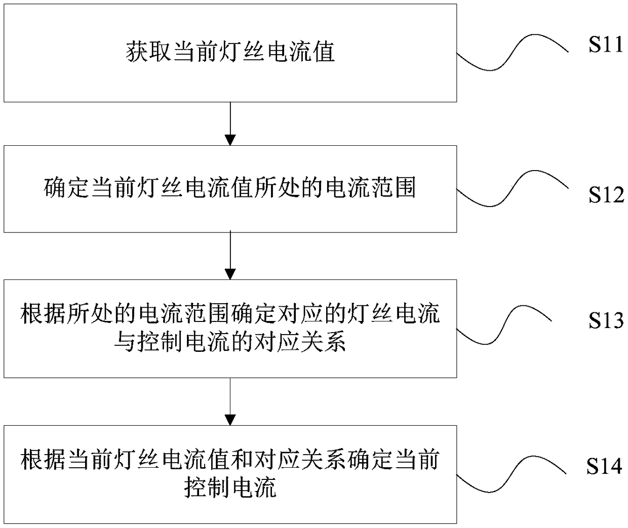
[0029] An embodiment of the present invention provides a filament current control method, figure 2 A flow chart of an optional filament current control method in an embodiment of the present invention, as shown in figure 2 As shown, the method includes:
[0030] Step S11, acquiring the current filament current value.
[0031] Specifically, the operating range of the filament current can be expressed as I a ~ I b . The current filament current value can be any current value within the working range.
[0032] Step S12, determining the current range of the current filament current value.
[0033] Specifically, the working range of the filament current can be divided into multiple current ranges, and the specific current range within the working range of the filament current can be determined according to the current value of the filament current.
[0034] Step S13, determining the correspondence between the corresponding filament current and the control current according ...
Embodiment 2
[0058] According to an embodiment of the present invention, a filament current control device is provided, Figure 4 A schematic diagram showing an optional filament current control device according to an embodiment of the present invention, as shown in Figure 4 As shown, the device includes:
[0059] The acquiring module 41 is configured to acquire the current filament current value; please refer to the description of step S11 in the first embodiment.
[0060] The analysis module 42 is configured to determine the current range of the current filament current value; please refer to the description of step S12 in the first embodiment.
[0061] The determination module 43 is configured to determine the correspondence between the corresponding filament current and the control current according to the current range; please refer to the description of step S13 in the first embodiment.
[0062] The processing module 44 is configured to determine the current control current accord...
Embodiment 3
[0069] The embodiment of the present invention also provides a server, such as Figure 5 As shown, the server may include a processor 51 and a memory 52, wherein the processor 51 and the memory 52 may be connected via a bus or in other ways, Figure 5 Take connection via bus as an example.
[0070] The processor 51 may be a central processing unit (Central Processing Unit, CPU). Processor 51 can also be other general processors, digital signal processor (Digital Signal Processor, DSP), application specific integrated circuit (Application Specific Integrated Circuit, ASIC), field programmable gate array (Field-Programmable Gate Array, FPGA) or Other chips such as programmable logic devices, discrete gate or transistor logic devices, discrete hardware components, or combinations of the above-mentioned types of chips.
[0071] The memory 52, as a non-transitory computer-readable storage medium, can be used to store non-transitory software programs, non-transitory computer-execu...
PUM
 Abstract
Description
Claims
Application Information