PCB heat dissipation method and device

A heat dissipation method and thermal connection technology, applied in the direction of circuit heating devices, printed circuit components, etc., can solve the problems of space and cost increase, and achieve the effect of small space occupation, low cost, and uniform temperature distribution

Active Publication Date: 2018-10-12
INST OF ELECTRICAL ENG CHINESE ACAD OF SCI
View PDF7 Cites 2 Cited by
  • Summary
  • Abstract
  • Description
  • Claims
  • Application Information

AI Technical Summary

Problems solved by technology

In order to obtain better heat dissipation capability, more auxiliary heat dissipation materials need to be used, and the space and cost will increase accordingly

Method used


Image

  • PCB heat dissipation method and device
  • PCB heat dissipation method and device
  • PCB heat dissipation method and device

Examples


Embodiment Construction

[0017] The present invention will be further described below in conjunction with the accompanying drawings and specific embodiments.

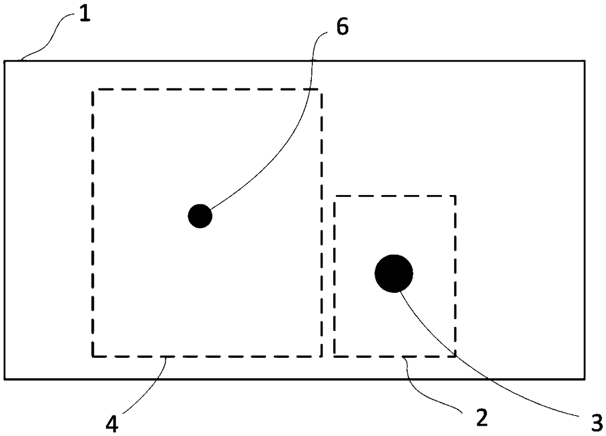
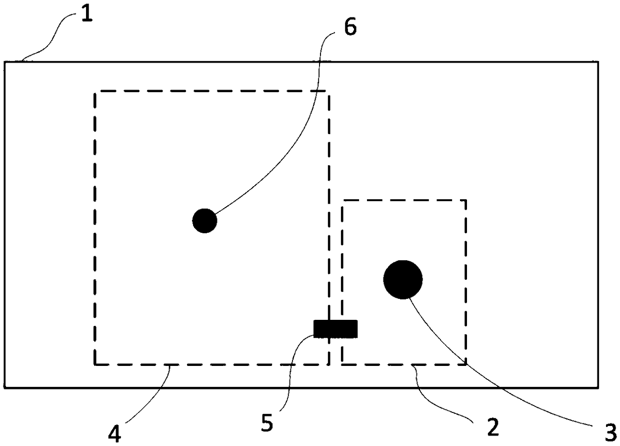
[0018] figure 2 Shown is an embodiment of the PCB heat dissipation method of the present invention. Such as figure 2 As shown, the PCB heat dissipation method of the present invention includes a PCB board 1 , a surface layer copper foil 2 , a surface layer copper foil 3 , a heat source device 4 , and a thermal connection element 5 .

[0019] The PCB board 1 is composed of a substrate and copper foil. The substrate has good electrical insulation properties and is used to carry electronic components. Copper foil has good electrical conductivity and is used for electrical connection between electronic components. The PCB board can be a single-layer PCB board or a multi-layer PCB board. For a single-layer PCB, the copper foil is located on the surface of the PCB. For multi-layer PCB boards, the copper foil can be located on the inner layer ...


PUM


Abstract

The invention relates to a PCB heat dissipation method and a PCB heat dissipation device, which are used for enhancing the heat dissipation ability of a heating device on the PCB and improving the environmental adaptability of a circuit board. By using a thermal connection element, the components of different electrical networks on the PCB are connected together, so that the components of different electrical networks share a heat dissipation network, and the thermal resistance of a single component to the environment is reduced, the heat distribution on the PCB is more uniform, the hot-spot temperature is reduced, and the PCB can be used in a higher ambient temperature.

Description

technical field [0001] The invention relates to the technical field of PCB heat dissipation, in particular to a method and a device for reducing the temperature of PCB hot spots by connecting isolated copper foils on the surface of the PCB through a thermal connection element. Background technique [0002] With the continuous development of electronic technology, the integration of electronic products is getting higher and higher, the design of circuit boards is becoming more and more compact, the function and quantity of devices on the PCB per unit area are increasing, and the heat dissipation of PCB is facing more and more problems. challenge. Especially for PCBs with power devices installed, the heat dissipation capability directly affects the maximum working environment temperature of the product as a whole. At present, the traditional PCB heat dissipation technologies mainly include: (1) installing a heat sink or radiator on the heating device, and relying on the heat ...

Claims


Application Information

Patent Timeline
Patent Type & Authority Applications(China)
IPC IPC(8): H05K1/02
CPCH05K1/0201H05K1/0209
Inventor 施其彪温旭辉
Owner INST OF ELECTRICAL ENG CHINESE ACAD OF SCI
Why Eureka
Try Eureka