
Rapid heat dissipation method and device based on semiconductor refrigeration technology

A technology of heat dissipation device and heat dissipation method, which is applied in the direction of cooling/ventilation/heating transformation, modification of power electronics, electrical components, etc., which can solve the problems of discounted cooling effect, generation of water vapor, condensation, and rapid heat dissipation, etc., to achieve control Convenience, improved equipment life, and stable operation

Active Publication Date: 2018-10-12
北京华悦龙驰科技有限公司
View PDF2 Cites 10 Cited by
  • Summary
  • Abstract
  • Description
  • Claims
  • Application Information

AI Technical Summary

Problems solved by technology

The cooling sheet has a feature that it can cool quickly in the first 3 minutes of starting up. If the cooling surface cannot dissipate the heat quickly, the cooling effect will be compromised
[0007] Since semiconductor cooling is forced cooling, the temperature at the heat-absorbing end may drop to a very low level, so water vapor and condensation will be generated at the heat-absorbing end, causing short circuit and corrosion of the circuit board.

Method used


Image

  • Rapid heat dissipation method and device based on semiconductor refrigeration technology
  • Rapid heat dissipation method and device based on semiconductor refrigeration technology
  • Rapid heat dissipation method and device based on semiconductor refrigeration technology

Examples


Embodiment 1

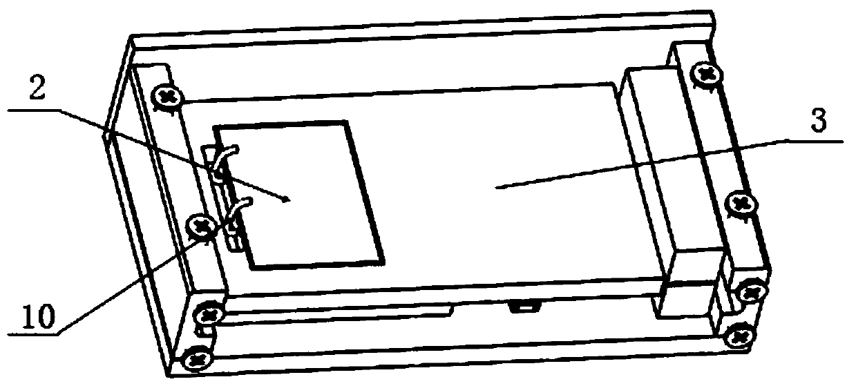
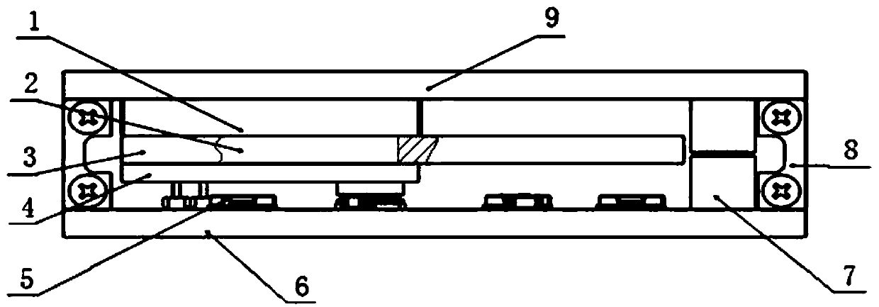
[0045] Such as figure 1 , figure 2 As shown, the copper foil of the aluminum-based circuit board 6 faces upward, and the power chip 5 is arranged on the copper foil surface by welding, and the heat generated by the power chip 5 can pass through the copper foil-aluminum-based circuit board of the aluminum-based circuit board 6 6. Aluminum base plate - This pathway emits emissions from the outside world. The aluminum-based circuit board 6 is connected to the top wall 9 through the side wall 8, and the top wall 9 is made of metal, that is, the outer wall for heat dissipation. The side wall 8 is made of heat insulating material, which prevents heat exchange between the top wall 9 and the aluminum-based circuit board 6 . Of course, the side wall 8 can also be made of metal, which can help the top wall 9 dissipate heat. At this time, a small heat insulating pad is provided between the side wall 8 and the aluminum-based circuit board.

[0046] There is a whole heat insulation pa...

Embodiment 2

[0056] The circuit board can be an epoxy resin non-metallic circuit board. The non-metallic circuit board and the heat insulation pad form the inner cavity that wraps the power chip 5. At this time, the heat dissipation of the power chip 5 is mainly through the semiconductor cooling chip 2 in addition to the heat dissipation of the contact with the air. Heat dissipation to the top wall 9 .

Embodiment 3

[0058] Like Embodiment 1, the bottom surface of the aluminum-based circuit board 6 is also attached to the heat-absorbing end of a heat-conducting element.


PUM


Abstract

The invention relates to a rapid heat dissipation method based on a semiconductor refrigeration technology. A rapid heat dissipation device based on the semiconductor refrigeration technology includesa heat conduction element,a heat insulation mat and a heat dissipation outer wall; power chips and the heat dissipation outer wall are arranged oppositely,and the heat insulation mat is arranged between the power chips and the heat dissipation outer wall; the heat conduction element is arranged on the heat insulation mat,the heat absorption end of the heat conduction element fits the power chipsthrough a first heat conduction mat,and the heat dissipation end of the heat conduction element fits the heat dissipation outer wall through a second heat conduction mat; when the heat conduction element works,the heat absorption end transmits heat to the heat dissipation end in a single direction. By the adoption of the rapid heat dissipation method based on the semiconductor refrigeration technology,the heat dissipation speed can be controlled; when the power chips suddenly generate a large amount of heat,the heat can be effectively dissipated,the temperature of the power chips is lowered,the heat insulation met prevents the heat from returning to ensure running of equipment,and therefore the service life of the equipment is prolonged. When the equipment is a sealed space with poor heatdissipation capability,it can be ensured that the temperature of areas of the power chips is low. The rapid heat dissipation device based on the semiconductor refrigeration technology is more compactin structure and convenient to design and transform.

Description

technical field [0001] The invention relates to the field of heat dissipation of electrical components, in particular to a rapid heat dissipation device based on semiconductor refrigeration technology. [0002] The invention also provides a rapid heat dissipation method based on semiconductor refrigeration technology. Background technique [0003] During the working process of the motor driver, especially in the case of fast start and heavy load, the motor driver needs to output a large current instantaneously or continuously, and its power chip and power chip and other devices will continue to generate a lot of heat, which must be dissipated in a timely and effective manner. If the heat accumulation will affect the stability of the motor driver and burn out the internal electronic components, the heat dissipation structure and method are one of the key technologies that affect the performance of the motor driver. The traditional heat dissipation measures for motor drivers ...

Claims


Application Information

Patent Timeline
IPC IPC(8): H05K7/20
CPCH05K7/2089H05K7/20945
Inventor 李思奇
Owner 北京华悦龙驰科技有限公司
Learn More