
Construction method of pipe gallery construction using formwork trolley

A technology of formwork trolley and construction method, which is applied in earthwork drilling, shaft equipment, shaft lining, etc., can solve the problems of high cost of formwork trolley, increased self-weight of steel truss, and large number of jacks, etc., and achieves enhanced demoulding efficiency, Improving integrity and rapid demoulding effect

Active Publication Date: 2020-04-28
CHINA 19TH METALLURGICAL CORP CHENGDU CONSTR +1
View PDF1 Cites 0 Cited by
  • Summary
  • Abstract
  • Description
  • Claims
  • Application Information

AI Technical Summary

Problems solved by technology

In this method, during the use of the formwork trolley, the self-weight of the top formwork is completely transmitted to the side formwork, and then to the horizontal jack, so that it cantilever and bear the force. Therefore, the steel trusses such as the longitudinal beams in the middle are required to have good mechanical performance. More complex reinforcement measures require more complex structures and higher material requirements, which also increase the self-weight of the steel truss itself; in addition, the jacks supporting the top form and the jacks for the side forms not only have axial force, but also are subject to bending moments, so , requires a large number of jacks and large specifications, resulting in high cost of formwork trolley and difficult operation

Method used


Image

  • Construction method of pipe gallery construction using formwork trolley
  • Construction method of pipe gallery construction using formwork trolley
  • Construction method of pipe gallery construction using formwork trolley

Examples


Embodiment Construction

[0027] Below in conjunction with accompanying drawing and embodiment the present invention is described further as follows:

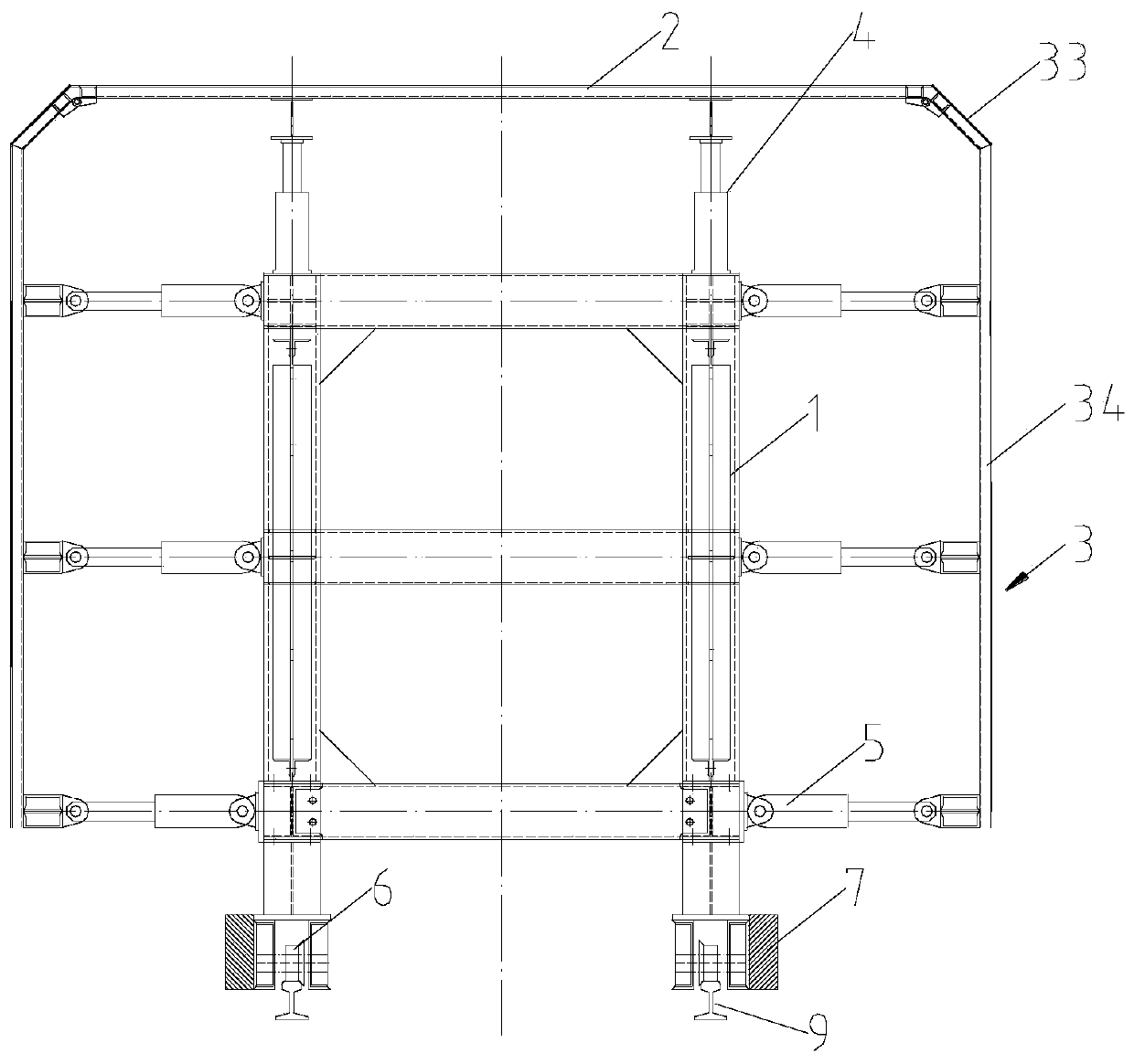
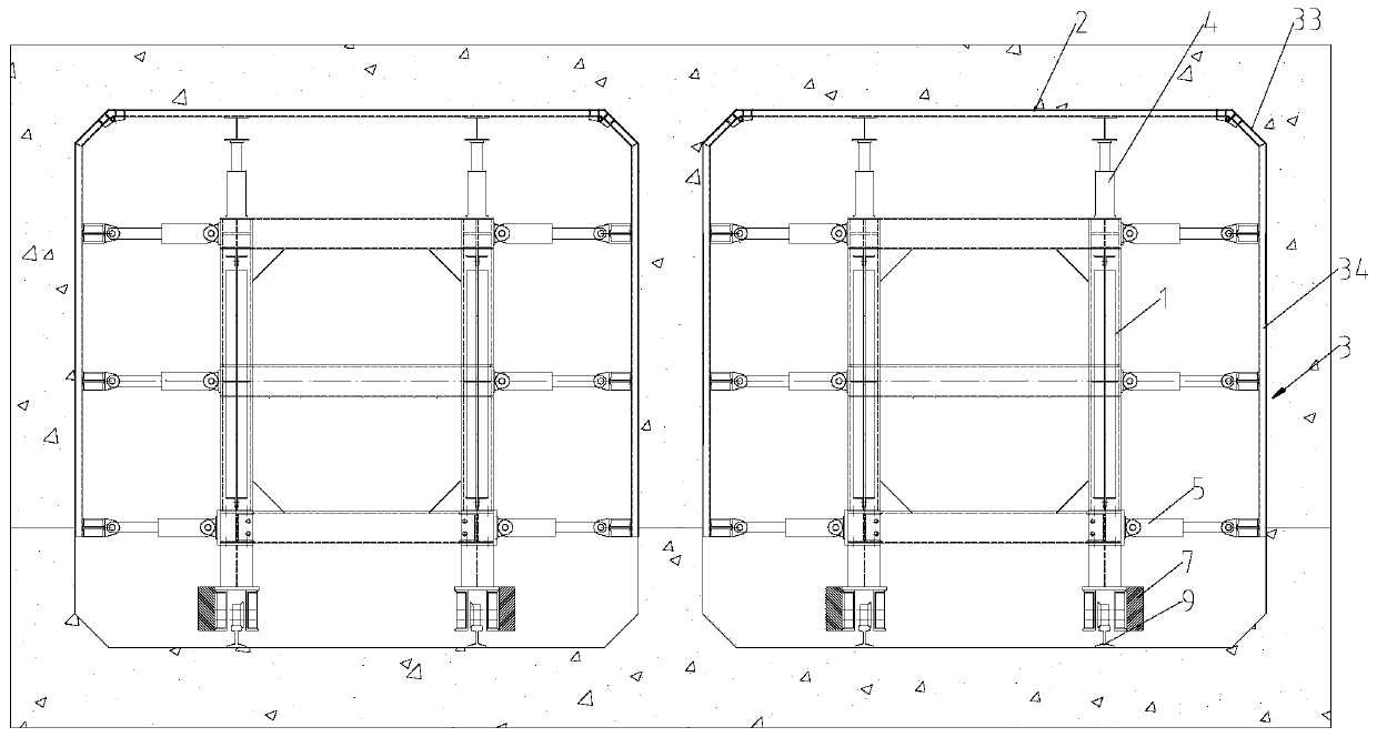
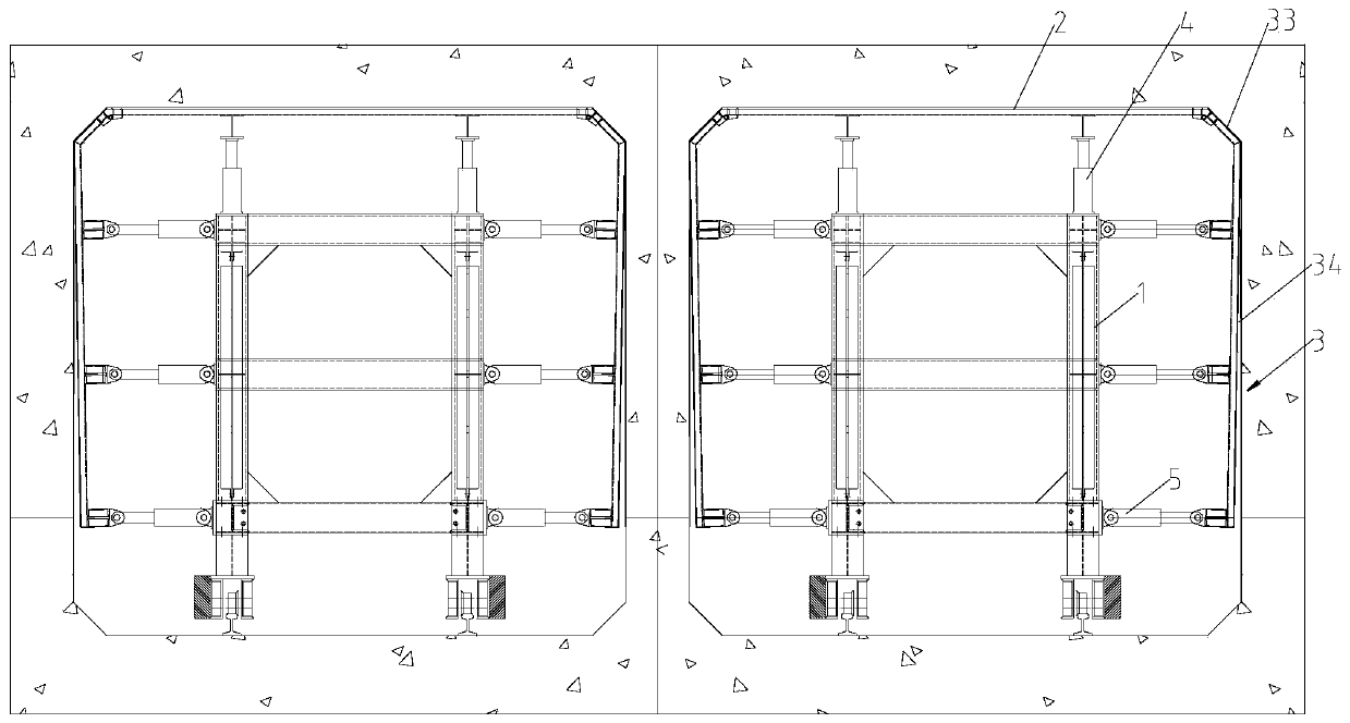
[0028] Such as figure 1 , figure 2 , image 3 , Figure 4 and Figure 5 As shown, the construction method disclosed in the present invention is to use a formwork trolley for pipe gallery construction. The formwork trolley is formed by detachable docking of multiple trolley sections; each trolley section includes a steel truss 1 in the middle, The top form 2 arranged above the steel truss 1 and the side forms 3 arranged on both sides of the steel truss 1, the two ends of the top form 2 are hingedly connected with the top ends of the corresponding side forms 3 respectively; The horizontal hydraulic jacks 5 arranged in groups, each horizontal hydraulic jack 5 in the group is vertically arranged along the side form 3, and one end of the horizontal hydraulic jack 5 is connected with the steel truss 1, and the other end is hinged with the side form 3; T...


PUM


Abstract

The invention discloses a construction method for pipe gallery construction through a formwork trolley, and belongs to the field of pipe gallery construction. The construction method aims to improve the forming quality of concrete and improve the construction efficiency. The construction method comprises the following sequentially-conducted steps that 1, a horizontal hydraulic jack is retracted, so that a lateral formwork rotates slightly with the hinged position of the lateral formwork and a top formwork as the axis so as to be disengaged from a concrete pouring layer; and 2, the top formworkis lowered, so that the top formwork is disengaged from the concrete pouring layer until the formwork trolley for pipe gallery construction can travel freely. According to the construction method, firstly, the top formwork and the lateral formwork are hinged into a whole, so that the integrality and the strength and rigidity properties of the formwork trolley are improved, formwork expansion is avoided, and splicing seams are less; secondly, the self weight of the trolley is low relatively, maneuverability and flexibility are good, so that the efficiency of jack supporting and formwork disengaging is improved, and the moving speed is increased; thirdly, the horizontal hydraulic jack is downsized and miniaturized, materials used by the formworks and a truss are subjected to optimization design, thus waste is avoided, and the manufacturing cost is lowered significantly; and fourthly, through a formwork disengaging mode, stress is safer and more reasonable, and formwork disengaging is quicker and more reliable.

Description

technical field [0001] The invention belongs to the field of pipe gallery construction, in particular to a construction method for pipe gallery construction using formwork trolleys. Background technique [0002] The formwork trolley refers to non-standard equipment for movable formwork for reinforced concrete structures with the same cross-section in narrow and long structures such as tunnels or pipe galleries. Its purpose is to replace the traditional formwork support method, and use the stereotyped formwork construction equipment to set the formwork in place at one time for steel bar binding and concrete pouring. [0003] The formwork trolley used in pipe gallery engineering is in the stage of vigorously rising in China. For example, the application number is CN201710705771.4, and the name is a patent application for a formwork trolley for full-section construction of pipe gallery and its construction method. It discloses a pipe gallery. The construction method of the for...

Claims


Application Information

Patent Timeline
Patent Type & Authority Patents(China)
IPC IPC(8): E21D11/10
CPCE21D11/10E21D11/102
Inventor 代祖发黄朝阳
Owner CHINA 19TH METALLURGICAL CORP CHENGDU CONSTR
Learn More