
Pumping and cyclone conveying combined concrete spraying machine and spraying method thereof

A technology of concrete and combined pump, applied in the field of mining machinery and equipment, can solve the problems of difficult concrete material slump, complex process, material segregation, etc., to improve the efficiency of shotcrete operation, to have broad application prospects, and to solve the problem of pumping blockage. Effect

Pending Publication Date: 2018-10-16
CHINA UNIV OF MINING & TECH +1
View PDF29 Cites 3 Cited by
  • Summary
  • Abstract
  • Description
  • Claims
  • Application Information

AI Technical Summary

Problems solved by technology

When the material slump is too large, it is easy to cause segregation of the material, and it cannot be bonded on the surface of the cave wall after spraying; when the material slump is too small, the pumping resistance increases, and it is easy to cause pipe blockage or even pipe burst failure
In field application, it is difficult to strictly control the slump of concrete materials.
[0006] (3) The spraying distance is short
[0007] (4) The construction process is complicated
The pipeline needs to be wetted with cement slurry before pumping, and the pipeline needs to be cleaned with clean water after pumping, which is not only a complicated process but also a waste of materials

Method used


Image

  • Pumping and cyclone conveying combined concrete spraying machine and spraying method thereof
  • Pumping and cyclone conveying combined concrete spraying machine and spraying method thereof
  • Pumping and cyclone conveying combined concrete spraying machine and spraying method thereof

Examples


Embodiment Construction

[0026] The present invention will be further explained below in conjunction with the accompanying drawings.

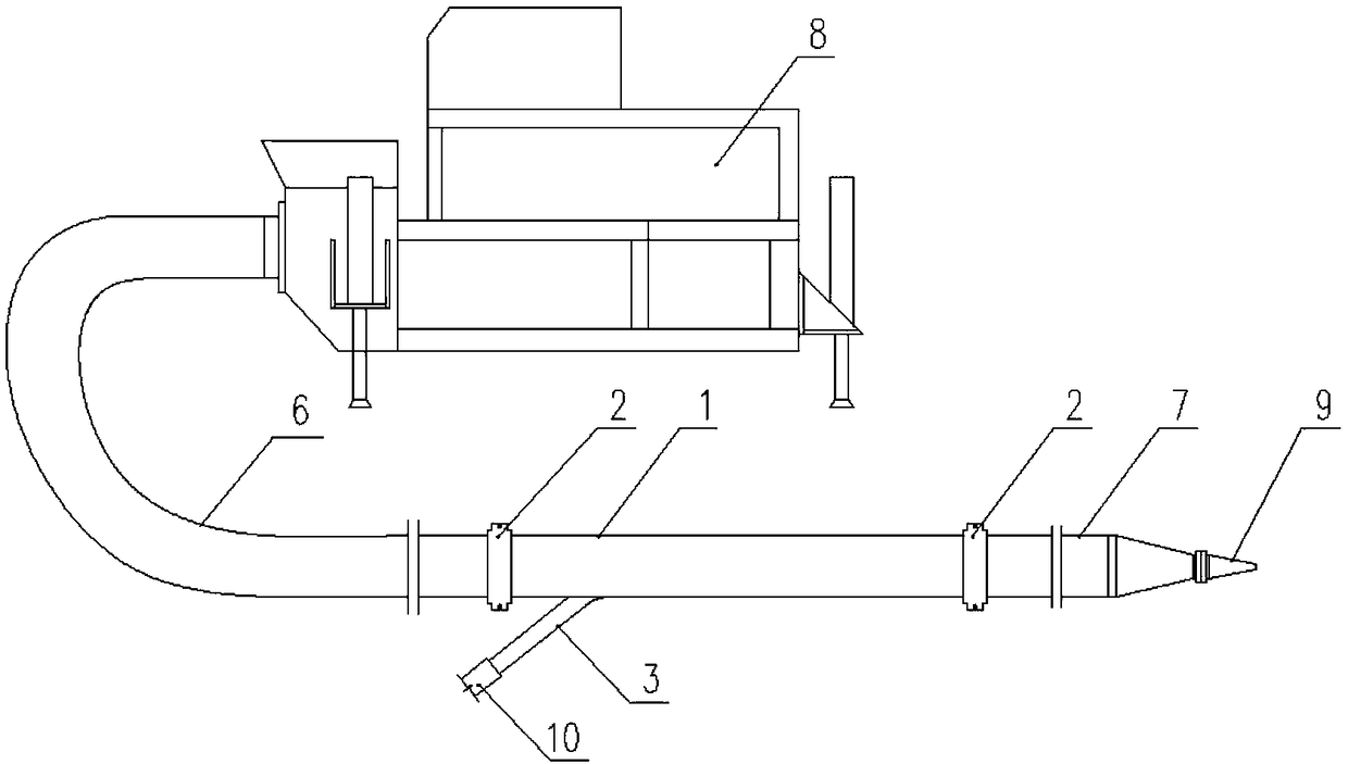
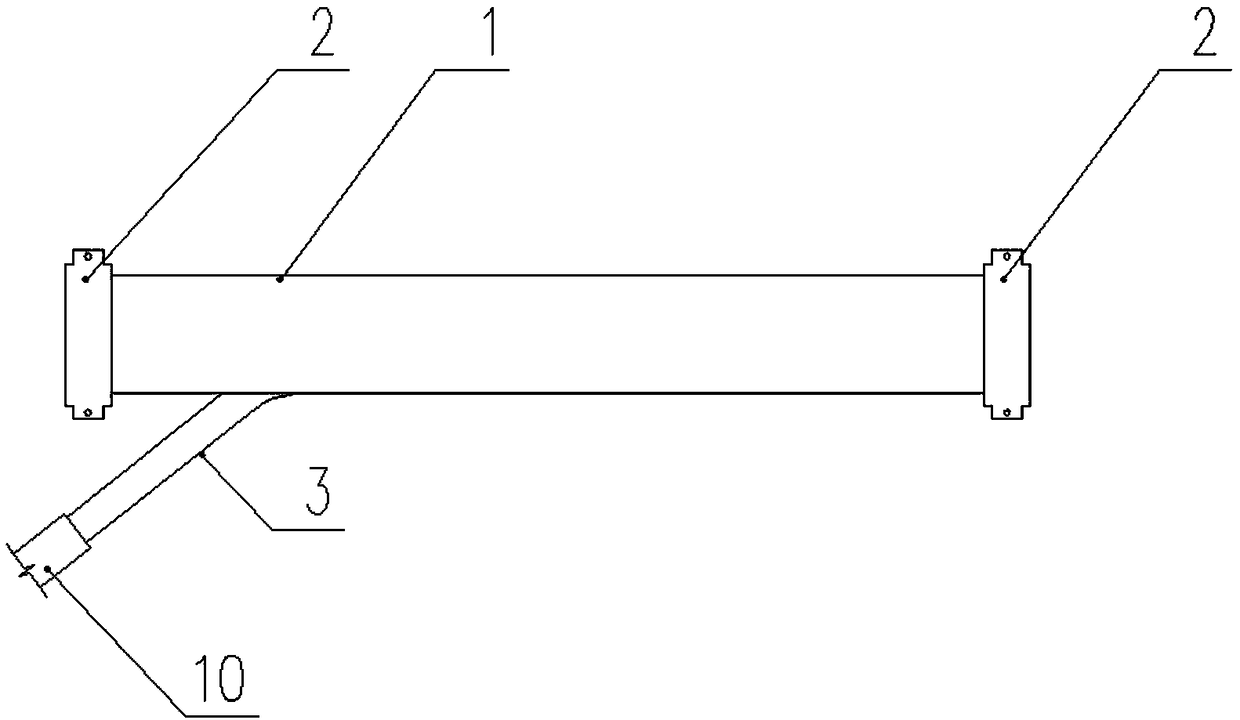
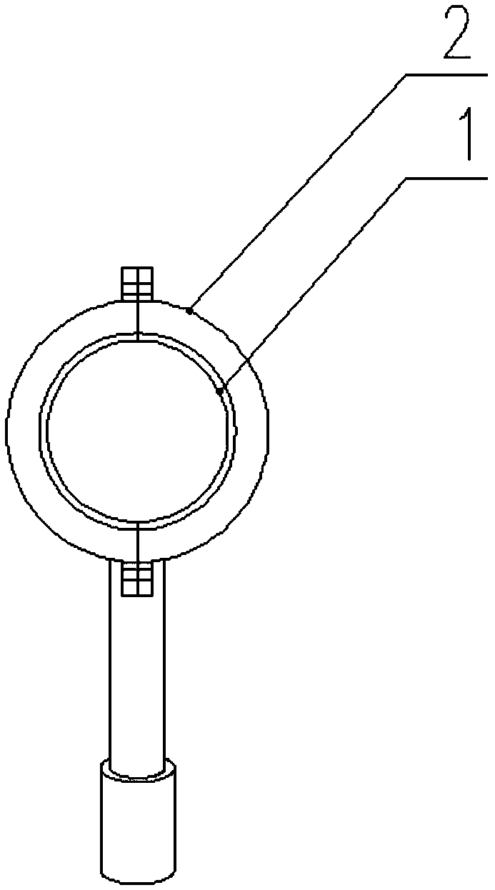
[0027] A concrete shotcrete machine combined with pumping and cyclone conveying, such as figure 1 As shown, it consists of a pumping system and a cyclone conveying system. Wherein, the pumping system includes a concrete pumping machine 8 and a pump material pipe 6 , and the cyclone conveying system includes a threaded cyclone pipe 1 , a feeding pipe 7 , an air inlet pipe 3 and a nozzle 9 . Such as Figure 4 As shown, the inner side of the threaded cyclone pipe 1 is processed with a spiral inner groove 5, which is used to control the rotation of the airflow and enhance the carrying capacity of the gas. An air intake pipe 3 is welded on the side wall of the threaded cyclone pipe 1, and the axial direction of the air intake pipe 3 is at a certain angle with the axial direction of the threaded cyclone pipe 1. The feeding pipe 7 connects the threaded cyclone pipe 1 and t...


PUM


Abstract

The invention discloses a pumping and cyclone conveying combined concrete spraying machine and a spraying method thereof. The combined pumping and cyclone conveying concrete spraying machine comprisesa pumping system and a cyclone conveying system. The pumping system comprises a concrete pumping machine and a material pumping pipe. The cyclone conveying system comprises a threaded cyclone pipe, aconveying pipe, an air delivering pipe and a nozzle. A spiral inner groove is machined in the inner side of the threaded cyclone pipe and used for controlling airflow rotation. An air inlet pipe is welded to the pipe wall of one side of the threaded cyclone pipe. A certain angle is formed between the axis direction of the air inlet pipe and the axis direction of the threaded cyclone pipe. The airinlet pipe is connected with the air delivering pipe. The threaded cyclone pipe and the nozzle are connected through the conveying pipe to constitute the cyclone conveying system. The concrete pumping machine and the cyclone conveying system are connected through the material pumping pipe so that combined conveying of concrete can be achieved. According to the pumping and cyclone conveying combined concrete spraying machine and the spraying method thereof, the advantages of high material supplying speed and even materials of the pumping system and the advantages of large cyclone conveying distance, no pipe plugging and no pipe washing are combined, and the problems that as for an existing pumping wet spraying machine, pipe plugging is liable to occur, and the construction process is complex are effectively solved.

Description

technical field [0001] The patent of the present invention relates to the technical field of mining machinery and equipment, and more specifically, relates to a concrete spraying machine and a spraying method combined with pumping and cyclone conveying. Background technique [0002] At present, there are mainly two types of concrete spraying construction technology, one is dry spraying method construction, and the other is wet spraying method construction. The dry spraying method refers to mixing the spraying material according to a certain mixing ratio in the absence of water, and then the mixing material is conveyed to the nozzle of the spray gun by pneumatic force, mixed with pressure water and sprayed out. The wet spray method means that the concrete is first stirred evenly, and then sprayed to the designated position by a spray machine. Compared with the wet spraying method, the dry spraying method will cause a large amount of dust during construction, and the amount o...

Claims


Application Information

Patent Timeline
Patent Type & Authority Applications(China)
IPC IPC(8): E21D11/10
CPCE21D11/105
Inventor 张凯薛欣然冯兴科
Owner CHINA UNIV OF MINING & TECH
Learn More