Programmable delay setting circuit and working method

A circuit and capacitor technology, applied in the field of programmable delay setting circuit, to achieve good application prospects and economic benefits, the effect of changing the discharge time

Active Publication Date: 2018-10-16
XIAN MICROELECTRONICS TECH INST
View PDF5 Cites 2 Cited by
  • Summary
  • Abstract
  • Description
  • Claims
  • Application Information

AI Technical Summary

Problems solved by technology

In the traditional PWM switching power supply, the switching loss is one

Method used


Image

  • Programmable delay setting circuit and working method
  • Programmable delay setting circuit and working method
  • Programmable delay setting circuit and working method

Examples


Embodiment

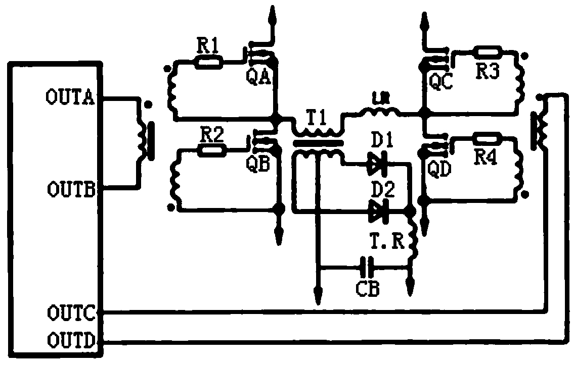
[0028] The invention can be used for the circuit design of the switching power supply chip, and is especially suitable for the circuit design of the phase-shifting resonant PWM controller, which is the core control chip of the phase-shifting full-bridge converter.

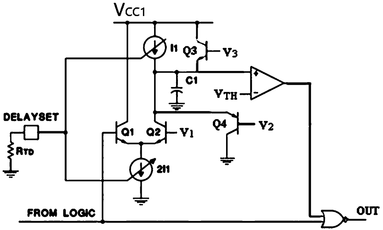
[0029] By adopting the above invention, a circuit design is carried out for the delay setting function of a certain phase-shifting resonant PWM controller circuit. Such as image 3 As shown, design capacitance C1=5pF, threshold voltage V 2 =5.0V, threshold voltage V 3 = 3.3V, threshold voltage V TH =3.05V, internal constant current source design n=13, V DELAYSET =2.5V, when the external delay resistor R TD When it is 4.8kΩ, I can be calculated according to formula (2) 1 It is about 40μA, and the delay time t can be calculated according to the formula (3) d about 390ns; when R TD When it is 1.9kΩ, I can be calculated according to formula (2) 1 It is about 100μA, and the delay time t can be calculated accordi...


PUM


Abstract

The invention discloses a programmable delay setting circuit and a working method. The method changes the magnitude of discharge current of a constant current source to a delay capacitor in a circuitby changing the size of an external delay resistor, thereby changing the discharge time and controlling a phase difference of four path output time of a phase shift resonant PWM controller. Moreover,zero delay setting can also be achieved by setting a DELAYSET end open circuit or an external high level voltage to turn off the constant current source. Circuit test results show that under differentexternal delay resistor conditions, the delay can be flexibly achieved at any time, including zero delay. The method can be fully compatible with a standard bipolar process, can be widely applied toa high-efficiency switching power supply chip design, and have good application prospects and economic benefits.

Description

technical field [0001] The invention belongs to the circuit design field of switching power supply chips, and in particular relates to a programmable delay setting circuit and a working method. Background technique [0002] To realize the miniaturization of the switching power supply, in addition to improving the performance and volume of the components themselves, another important way is to increase the operating frequency of the switching power supply. In the traditional PWM switching power supply, switching loss is one of the main obstacles to high frequency switching power supply. The dead time reserved to prevent the common conduction of the switching tubes limits the improvement of the operating frequency of the switching power supply, and the phase-shifting resonant PWM technology uses the dead time to make the output capacitance (parasitic parameters) of the switching tubes through the resonant cavity. The voltage is rapidly discharged, thereby realizing zero-volta...

Claims


Application Information

Patent Timeline
IPC IPC(8): H02M1/08
CPCH02M1/083H02M1/0058Y02B70/10
Inventor 师娅武琪
Owner XIAN MICROELECTRONICS TECH INST
Why Eureka
Try Eureka