Coating waste gas filter device

A waste gas filtration and coating technology, which is applied in the direction of combination device, gas treatment, membrane technology, etc., can solve the problems of insufficient contact between painting waste gas and filter screen, poor treatment effect of painting waste gas, and poor filtering effect of filter screen, etc. Achieve the effect of improving the filtering effect, improving the processing effect and improving the reliability of use

Pending Publication Date: 2018-10-19
JIANGSU SELF ENVIRONMENTAL SCI & TECHCO
View PDF0 Cites 3 Cited by
  • Summary
  • Abstract
  • Description
  • Claims
  • Application Information

AI Technical Summary

Problems solved by technology

[0002] As we all know, the painting waste gas filter device is an auxiliary device used to filter the waste gas in the spraying workshop so as to better process the waste gas generated by spraying, and it has been widely used in the field of environmental protection; the existing The coating exhaust gas filtering device includes a treatment box, a filter screen is arranged horizontally inside the treatment box, an air inlet and an air outlet are respectively provided at the top and bottom of the treatment box, and both the air inlet and the air outlet are connected to the inside of the treatment box. An air intake pipe is connected to the air inlet, and an air intake pump is connected to the air intake pipe; when using the existing exhaust gas filter device for painting, firs

Method used


Image

  • Coating waste gas filter device
  • Coating waste gas filter device
  • Coating waste gas filter device

Examples


Example Embodiment

[0017] The specific embodiments of the present invention will be described in further detail below in conjunction with the drawings and embodiments. The following examples are used to illustrate the present invention, but not to limit the scope of the present invention.
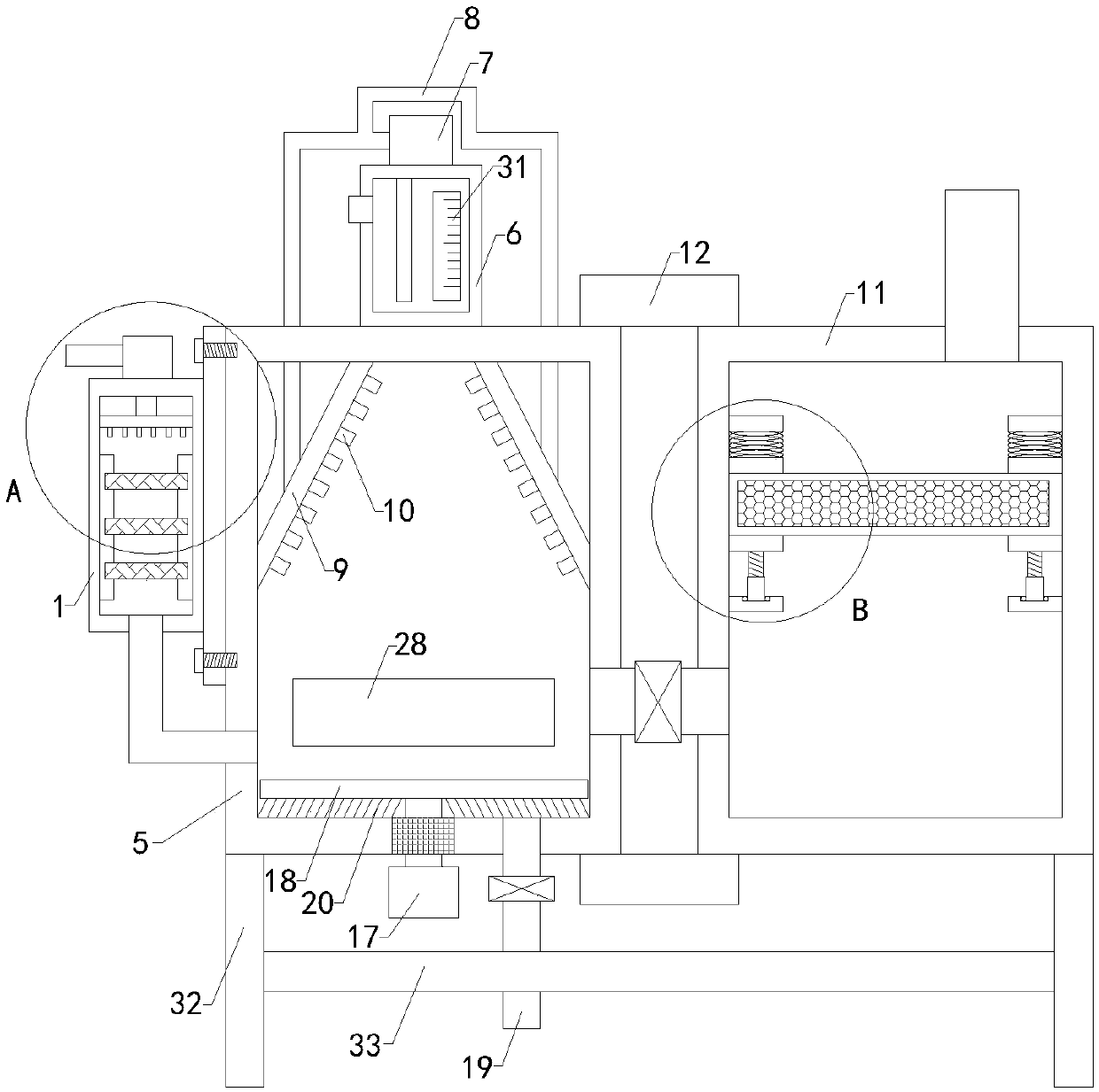
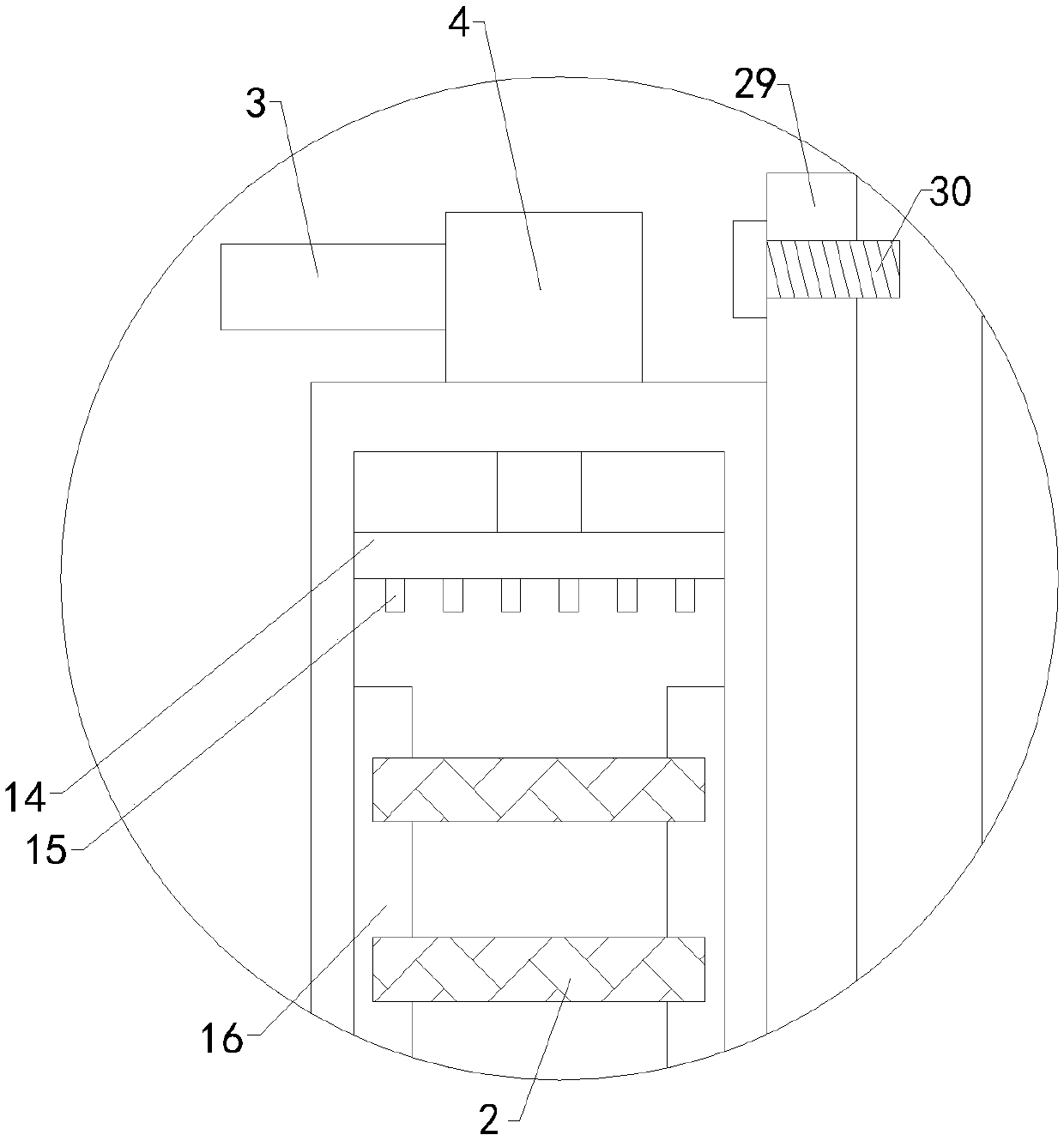
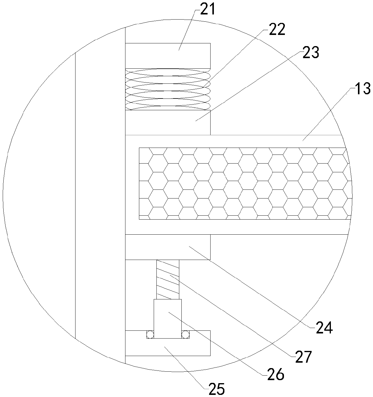
[0018] Such as Figure 1 to Figure 3 As shown, a coated exhaust gas filter device of the present invention includes a processing box 1, a filter screen 2 is arranged transversely inside the processing box, an air inlet and an air outlet are respectively provided at the top and bottom ends of the processing box, and the air inlet Both the air outlet and the air outlet are communicated with the inside of the processing box, the air inlet is connected with an air inlet pipe 3, and the air inlet pipe is connected with an air inlet pump 4; including a spray box 5, a water tank 6, a spray pump 7, and two sets of spray pipes 8. The left spray plate 9 and the right spray plate, the spray box is installed at the right e...


PUM


Abstract

The invention relates to the technical field of environmental-protection accessory device, and in particular, relates to a coating waste gas filter device which can remove more granular impurities contained in coating waste gas and improve the filter effect; at the same time, the coating waste gas filter device can remove pungent smell contained in the coating waste gas, prevent direct discharge of the pungent smell from causing harm of human body health and improve the reliability of use; moreover, the coating exhaust gas makes full contact with a filter screen, so the treatment effect of thecoating exhaust gas is improved. The coating waste gas filter device includes a treatment tank; the interior of the treatment tank is transversely provided with the filter screen. The coating waste gas filter device includes a spray tank, a water tank, a spray pump, two groups of spray pipes, a left spray disk, a right spray disk, a purification tank, an upper connecting plate, a lower connectingplate, and a metal net frame; the interior of the metal net frame is filled with an activated carbon adsorbent. The coating waste gas filter device also includes a flow equalizing cover, a pluralityof groups of air outlet nozzles, a left mounting hanging plate and a right mounting hanging plate; the flow equalizing cover is transversely arranged on the upper side of the interior of the treatmenttank, and the input end of the top of the flow equalizing cover is connected with the output end of a gas intake pipe.

Description

technical field [0001] The invention relates to the technical field of environmental protection attachments, in particular to a painting waste gas filtering device. Background technique [0002] As we all know, the painting waste gas filter device is an auxiliary device used to filter the waste gas in the spraying workshop so as to better process the waste gas generated by spraying, and it has been widely used in the field of environmental protection; the existing The coating exhaust gas filtering device includes a treatment box, a filter screen is arranged horizontally inside the treatment box, an air inlet and an air outlet are respectively provided at the top and bottom of the treatment box, and both the air inlet and the air outlet are connected to the inside of the treatment box. An air intake pipe is connected to the air inlet, and an air intake pump is connected to the air intake pipe; when using the existing exhaust gas filter device for painting, first connect the i...

Claims


Application Information

Patent Timeline
IPC IPC(8): B01D50/00B01D53/04
CPCB01D53/04B01D2253/102B01D2258/0258B01D50/60
Inventor 吕海波宋友高
Owner JIANGSU SELF ENVIRONMENTAL SCI & TECHCO
Why Eureka
Try Eureka