Cleaning and drying and automatic merging equipment for expansion-broken crank connecting rod

A crank connecting rod and breaking technology, which is applied in lighting and heating equipment, cleaning methods using liquid, drying, etc., can solve the problems of low efficiency, disordered sequence of cap end and rod end, and inability to match cap end and rod end and other issues to achieve the effect of improving efficiency and high efficiency

Inactive Publication Date: 2018-10-19
邱丹
View PDF1 Cites 5 Cited by
  • Summary
  • Abstract
  • Description
  • Claims
  • Application Information

AI Technical Summary

Problems solved by technology

However, the broken crank connecting rod cannot be replaced due to the one-to-one correspondence between the cap end and the rod end. The existing technology automatically cleans and assembles it, which easily leads to confusion in the order of the cap end and the rod end, resulting in the inability to match the cap end and the rod end. Therefore, cleaning, drying and assembly are often performed manually to ensure that the assembled cap end and rod end can correspond one-to-one, but the efficiency is low

Method used


Image

  • Cleaning and drying and automatic merging equipment for expansion-broken crank connecting rod
  • Cleaning and drying and automatic merging equipment for expansion-broken crank connecting rod
  • Cleaning and drying and automatic merging equipment for expansion-broken crank connecting rod

Examples


Embodiment Construction

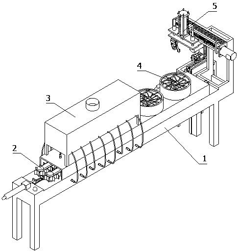
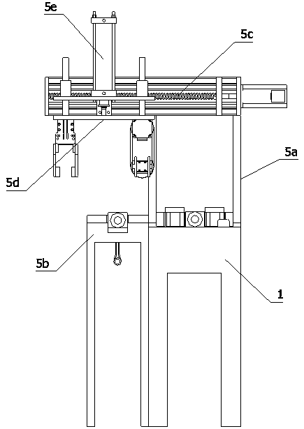
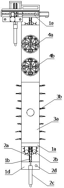
[0022] Below in conjunction with accompanying drawing and embodiment of description, specific embodiment of the present invention is described in further detail:

[0023] refer to Figure 1 to Figure 11 It can be seen that the cleaning, drying and automatic merging device for the broken crank connecting rod provided by the present invention includes a table 1 and a transmission device 2 installed on the table 1, a cleaning device 3, a drying device 4 and an automatic merging device 5; The transmission device 2 includes a guide rail 2a distributed along the direction from the head to the tail of the table 1 and used to place the cover end and the rod end of the pop-off crank connecting rod 6, and to drive the cover end and the rod end along the guide rail 2a from The head of the table 1 moves to the driving device 2b at the tail, the cleaning device 3 and the drying device 4 are installed above the head and the tail of the table 1 respectively, and the transmission device 2 is ...


PUM


Abstract

The invention relates to the technical field of crankshaft machining equipment, in particular to cleaning and drying and automatic merging equipment for an expansion-broken crank connecting rod. The cleaning and drying and automatic merging equipment comprises a guide rail for placing the expansion-broken crank connecting rod and a driving device for driving a crankshaft connecting rod to move from the head portion to the tail portion of the table platform, and further comprises an assembly stand mounted on the side of the table platform, a vertical grabbing manipulator for grabbing the rod end and a rotary grabbing manipulator which grabs and rotates the cover end by 180 degrees and moves the cover end to the assembly stand. A horizontal moving device and a vertical moving device which are used for driving the manipulators to move are further installed on the tail portion of the table platform. Workers sequentially place the cover end and the rod end on the guide rail in the directionin which the cross sections face upwards, and a transmission device drives the cover end and the rod end to pass through a cleaning device and a drying device. The vertical grabbing manipulator places the rod end on the assembly stand, and the rotary grabbing manipulator rotates the cover end by 180 degrees to place on the rod end to complete merging. The cover end and the rod end of a same groupcorrespond to each other in a one-to-one mode in the whole process of being placed, cleaned, dried and taken out and are not be mixed.

Description

technical field [0001] The invention relates to the technical field of crankshaft processing equipment, in particular to cleaning, drying and automatic merging equipment for cracking crank connecting rods. Background technique [0002] The crankshaft connecting rod is the main moving part of the engine. Its function is to convert the reciprocating motion of the piston into the rotational motion of the crankshaft, and at the same time convert the force acting on the piston into the torque output by the crankshaft to drive the wheels of the car. During the machining process, the crank connecting rod needs to be broken into two parts, the cover end and the rod end at the large shaft hole. After installing the cover end and the rod end on the crankshaft, tighten the cover end and the rod end with bolts to complete the assembly. The crank connecting rod The processing technology of breaking the large shaft hole is divided into two types: cutting and expanding. The cut off crank c...

Claims


Application Information

Patent Timeline
Patent Type & Authority Applications(China)
IPC IPC(8): B08B3/02B08B13/00F26B21/00B23P19/00B23P19/027
CPCB08B3/022B08B13/00B23P19/00B23P19/001B23P19/027F26B21/00
Inventor 邱丹
Owner 邱丹
Why Eureka
Try Eureka