
Micro-beam arc selective fusing and electric spark layered milling composite additive manufacturing method

An additive manufacturing and electric spark technology, which is applied in the field of micro-beam arc selective melting and EDM layered milling composite additive manufacturing, can solve problems such as warping, bulging and pilling of metal parts, and achieve increased density , Eliminate bulge and warpage, improve the effect of forming accuracy

Active Publication Date: 2018-10-19
HARBIN INST OF TECH
View PDF9 Cites 5 Cited by
  • Summary
  • Abstract
  • Description
  • Claims
  • Application Information

AI Technical Summary

Problems solved by technology

[0005] In order to solve defects such as local bumps and warping of metal parts easily caused by existing additive manufacturing methods, the present invention provides a composite additive manufacturing method of micro-beam arc selective melting and EDM layered milling

Method used


Image

  • Micro-beam arc selective fusing and electric spark layered milling composite additive manufacturing method
  • Micro-beam arc selective fusing and electric spark layered milling composite additive manufacturing method
  • Micro-beam arc selective fusing and electric spark layered milling composite additive manufacturing method

Examples


specific Embodiment

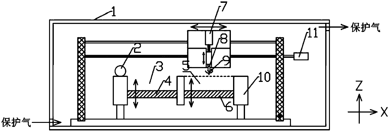
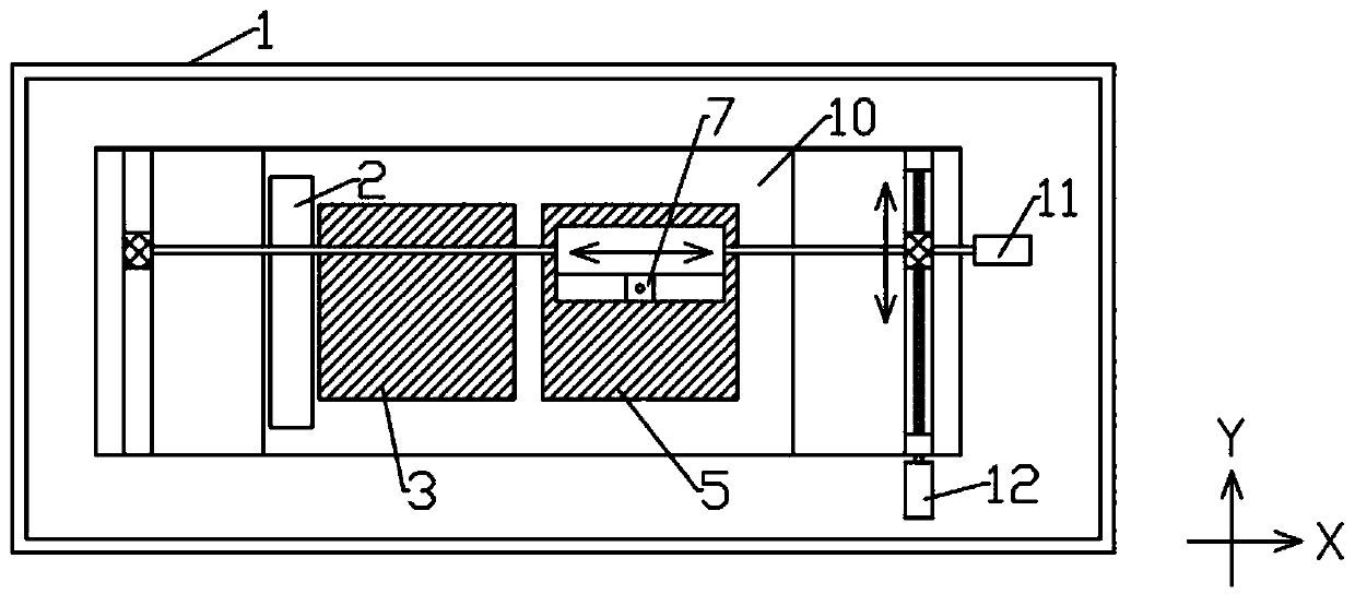
[0043] Specific embodiment: the composite additive manufacturing method of micro-beam arc selective melting and electric spark layered milling in this embodiment is realized by means of an additive manufacturing device, such as figure 1 and figure 2 As shown, the device includes an airtight chamber 1, a powder spreading preheating roller 2, a raw material chamber 3, a raw material chamber supporting plate 4, a forming cavity 5, a forming cavity supporting plate 6, a Z-axis servo feed mechanism 7, a high-speed spindle 8, Tool electrode 9, worktable base 10, X-direction feed part 11, Y-direction feed part 12; worktable base 10 is provided with two cavities, respectively: raw material cavity 3 and molding cavity 5, worktable base 10 The top surface is flat; the raw material cavity bottom plate 4 is set in the raw material cavity 3 and can move up and down; the molding cavity bottom plate 6 is set in the molding cavity 5 and can move up and down; the powder spreading preheating r...


PUM


Abstract

The invention provides a micro-beam arc selective fusing and electric spark layered milling composite additive manufacturing method and belongs to the technical field of metal part forming manufacturing. The method aims at overcoming the defects that by means of an existing additive manufacturing method, local convex bulging, warpage and the like of metal parts are caused easily. The method comprises the steps that according to a model to be processed, layering and the cross-sectional shape to be processed of each layer are determined according to a model to be processed; a layer of powder material is uniformly laid, and the laid powder layer is preheated; a tool electrode is arranged above the powder layer, a direct current power source supplies power to a tool electrode, and the tool electrode scans the powder layer according to the cross-sectional shape corresponding to the current powder layer, and the fusing forming of the layer is completed; the direct current power source is switched into a pulse power source, meanwhile a main shaft is rotated, the tool electrode is driven to rotate, and primary electro-charge milling is performed on the cross-sectional shape; and after electro-charge milling of the layer is completed, the next layer of powder is flatly laid on the upper surface of the powder layer until fusing and electro-discharge milling of all layers are completed, and the operations are finished.

Description

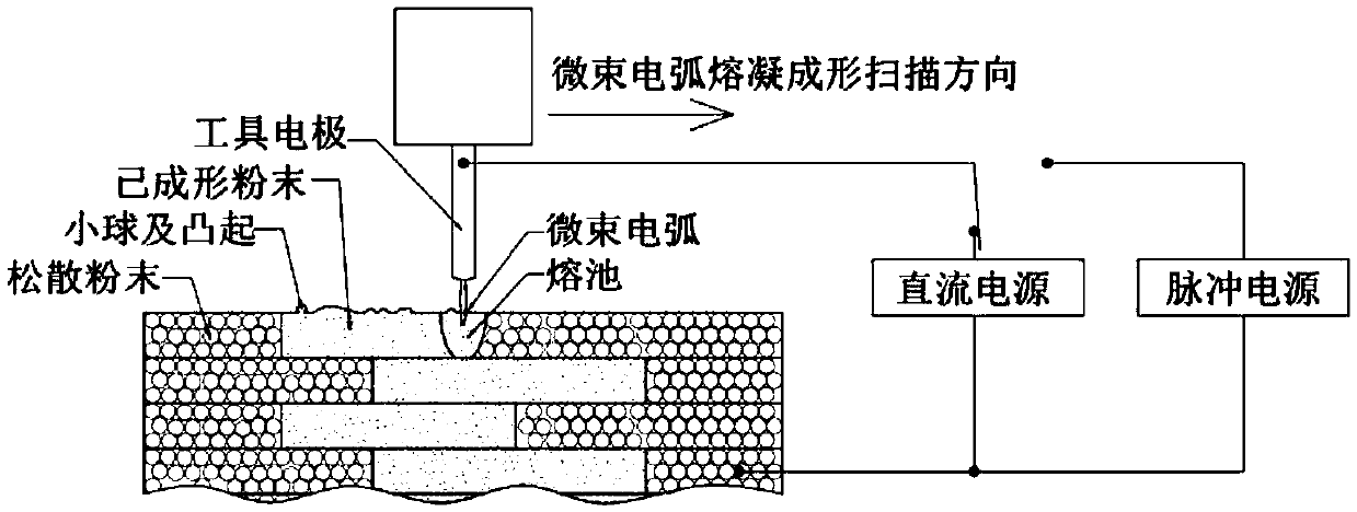
technical field [0001] The invention belongs to the technical field of forming and manufacturing of metal parts, and more specifically relates to a composite additive manufacturing method of micro-beam arc selective melting and electric spark layered milling of metal parts with high precision and high performance. Background technique [0002] Micro-beam arc selective melting additive manufacturing is a new type of additive manufacturing method for metal parts: it uses the micro-beam arc generated when the inter-electrode medium between the tool electrode and the metal powder is broken down by high voltage as a heat source, gradually The metal powder material is selectively scanned layer by layer, and the powder in the scanned area is melted and solidified together, and the solid parts are formed layer by layer. [0003] This method can form low laser absorption rate materials such as aluminum alloy and copper alloy, does not require a vacuum environment, does not require su...

Claims


Application Information

Patent Timeline
Patent Type & Authority Applications(China)
IPC IPC(8): B23H1/00B23H7/30B22F3/105B33Y10/00B33Y30/00
CPCB23H1/00B23H7/30B33Y10/00B33Y30/00B22F10/00B22F12/226B22F12/224B22F10/28B22F12/13B22F12/222B22F10/50Y02P10/25
Inventor 杨晓冬李世争
Owner HARBIN INST OF TECH
Learn More