
Multifunctional shearing machine

A shearing machine and multi-functional technology, which is applied in the direction of shearing devices, shearing machine accessories, other manufacturing equipment/tools, etc., can solve the problem that waste steel pipes cannot be flattened, it is inconvenient to return to the furnace for smelting, and the length of waste is different. problems, to achieve the effect of high work efficiency and automation, easy remelting and uniform length

Pending Publication Date: 2018-10-19
辽宁越华再生资源环保设备有限公司
View PDF7 Cites 1 Cited by
  • Summary
  • Abstract
  • Description
  • Claims
  • Application Information

AI Technical Summary

Problems solved by technology

[0003] However, in the prior art, there is no special equipment for the shearing of scrap steel, and ordinary cutting machines are usually used to complete it, which not only has high labor intensity, but also cuts out waste materials of different lengths, poor consistency, and inconvenient transportation; and The waste steel pipe cannot be flattened after cutting, which takes up a lot of space and is not easy to return to the furnace for smelting

Method used


Image

  • Multifunctional shearing machine
  • Multifunctional shearing machine
  • Multifunctional shearing machine

Examples


Embodiment Construction

[0027] The following will clearly and completely describe the technical solutions in the embodiments of the present invention with reference to the accompanying drawings in the embodiments of the present invention. Obviously, the described embodiments are only some, not all, embodiments of the present invention. Based on the embodiments of the present invention, all other embodiments obtained by persons of ordinary skill in the art without creative efforts fall within the protection scope of the present invention.

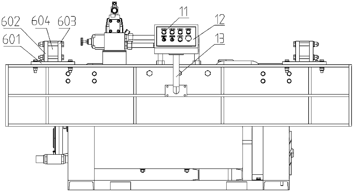
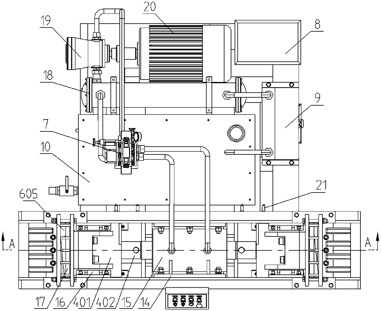
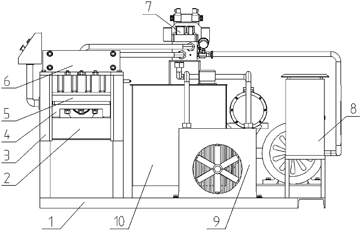
[0028] Such as Figure 1-Figure 5 As shown, a kind of multifunctional shearing machine that the present invention relates to comprises a frame 1, and is positioned at one side on frame 1 and is provided with cutting groove 3, and this cutting groove 3 is welded on frame 1 by the groove type The bracket and the side plates welded on both sides inside the groove bracket are composed. Both ends in the cutting groove 3 are respectively fixed with a fixed knife assembl...


PUM


Abstract

The invention discloses a multifunctional shearing machine. The multifunctional shearing machine comprises a machine frame, wherein a cutting groove is formed in the machine frame; fixed cutter assemblies are correspondingly fixed to the two ends in the cutting groove, and a driving oil cylinder is arranged in the middle of the cutting groove in the horizontal direction; the driving oil cylinder is a single-piston double-output-rod oil cylinder, and movable cutter assemblies are connected to the two ends of a piston rod of the driving oil cylinder correspondingly; squeezing plates are installed on the movable cutter assemblies and located above moving blades, and horizontal slideways are correspondingly arranged at the two sides of the movable cutter assemblies in the cutting groove; and feeding racks are correspondingly arranged on the inner sides of the fixed cutter assemblies on both ends above the cutting groove, and a plurality of vertically arranged feeding square holes are formed in each feeding rack in parallel for inserting a plurality of waste materials to be cut. The multifunctional shearing machine has the beneficial effects that the two-way work flattening and shearingof the driving oil cylinder can be realized, the working efficiency and the degree of automation are high, the labor intensity can be reduced, the length of the cut waste material is uniform, the consistency is good, and the transportation is convenient. Steel pipes and rebars of various specifications can be inserted and cut with wide processing range.

Description

technical field [0001] The invention relates to waste material processing equipment, in particular to a multifunctional shearing machine. Background technique [0002] In social production, a large amount of waste steel materials, such as steel pipes and steel bars, are produced every year. At present, the processing of these scrap steels is usually to cut the scrap into small pieces that are easy to melt, and then transport the small pieces of scrap to the steel factory, melt them into a liquid state, and then reprocess them into profiles that meet the requirements. [0003] However, in the prior art, there is no special equipment for the shearing of scrap steel, and ordinary cutting machines are usually used to complete it, which not only has high labor intensity, but also cuts out waste materials of different lengths, poor consistency, and inconvenient transportation; and After the waste steel pipe is cut, it cannot be flattened, and it takes up a lot of space, which is ...

Claims


Application Information

Patent Timeline
Patent Type & Authority Applications(China)
IPC IPC(8): B23P23/04B23D33/00
CPCB23D33/00B23P23/04
Inventor 卢玉森刘振兵
Owner 辽宁越华再生资源环保设备有限公司
Learn More