

Swinging type bath towel drying device
A drying device and swing-type technology, applied in the field of swing-type bath towel drying devices, can solve the problems of large contact area of bath towels, time consumption, and human health hazards, so as to improve the drying effect, reduce the contact area, The effect of improving efficiency
- Summary
- Abstract
- Description
- Claims
- Application Information
AI Technical Summary
Problems solved by technology
Method used
Image

Examples
Embodiment 1
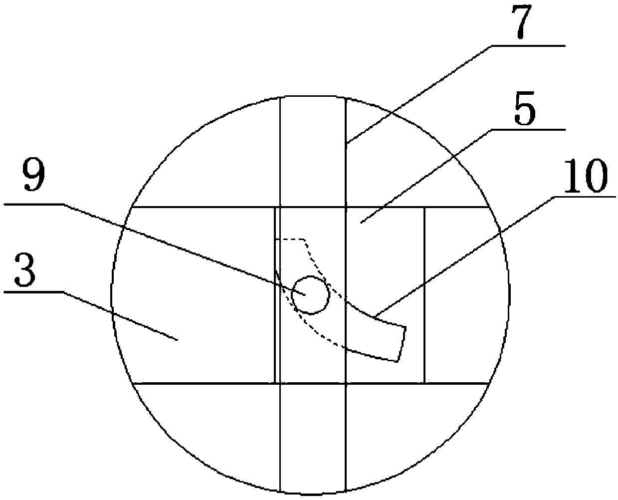
[0038] Such as Figure 7 As shown, the clamping mechanism 8 consists of a positioning plate 81 fixedly connected to the bottom end of the positioning rod 7, a first support plate 82 arranged on one side of the bottom of the positioning plate 81, a plurality of bolt holes 83 provided on the first support plate 82, and bolts. The screw 84 that is threaded on the hole 83, the second support plate 85 that is arranged on the other side of the bottom of the positioning plate 81, and the positioning column 86 that is arranged on the second support plate 85 and on the side opposite to the first support plate 82 are common. constitute.
Embodiment 2
[0040] Such as Figure 8 As shown, the clamping mechanism 8 is also composed of a U-shaped plate 87 fixedly connected to the bottom end of the positioning rod 7, a slide rail 88 fixedly connected to both sides of the inner wall of the U-shaped plate 87, and two symmetrical rails that are slidably connected to the two ends of the slide rail 88. The clamping plate 89, the tip block 810 fixedly connected to the opposite side of the clamping plate 89 and the second return spring 811, the shaft sleeve 812 symmetrically connected to the top of the inner wall of the U-shaped plate 87, and the pull rod 813 that one end passes through the shaft sleeve 812 and is connected to the side of the clamping plate 89 Together, the tip block 810 is positioned between the second return springs 811 .
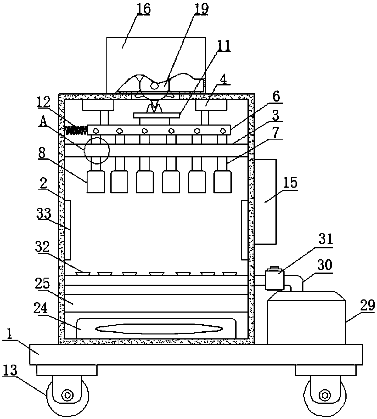
[0041] The driving mechanism is composed of a housing 16 arranged on the top of the casing 2, bearings 17 symmetrically arranged on both sides of the inner wall of the housing 16, a rotating shaft 1...
PUM
 Abstract
Description
Claims
Application Information