Eureka AIR delivers breakthrough ideas for toughest innovation challenges, trusted by R&D personnel around the world.

Self-restoring precast concrete beam-column joint device with top and bottom friction energy dissipation

A technology of prefabricated concrete and frictional energy consumption, which is applied in the direction of building components, earthquake resistance, building types, etc., can solve the problems of no steel structure, shear damage, insufficient load-bearing and shear capacity at nodes, etc., to improve the shear capacity, Avoid shear damage effects

Inactive Publication Date: 2018-10-19
SOUTHEAST UNIV
View PDF6 Cites 14 Cited by
  • Summary
  • Abstract
  • Description
  • Claims
  • Application Information

AI Technical Summary

Problems solved by technology

The prefabricated reinforced concrete frame has the advantages of fast production speed, stable quality, and formwork saving, but the reliability of the joint connection of the traditional prefabricated structure is poor, so the application in the earthquake area is limited
The beam-column connection is the most critical design link in the frame design of prefabricated concrete structures. The existing connection forms mostly refer to the joint structure of steel frames, but the concrete structure itself does not have the advantages of light weight and high strength of steel structures. At the same time, considering Vertical load-bearing is the most important factor in the design of concrete structures, so the connection method of steel structure beam-column joints is very likely to cause insufficient load-bearing and shear resistance at the joints, and then shear failure occurs

Method used


Image

  • Self-restoring precast concrete beam-column joint device with top and bottom friction energy dissipation
  • Self-restoring precast concrete beam-column joint device with top and bottom friction energy dissipation
  • Self-restoring precast concrete beam-column joint device with top and bottom friction energy dissipation

Examples


Embodiment Construction

[0037] The technical solution of the present invention will be described in detail below in conjunction with the accompanying drawings.

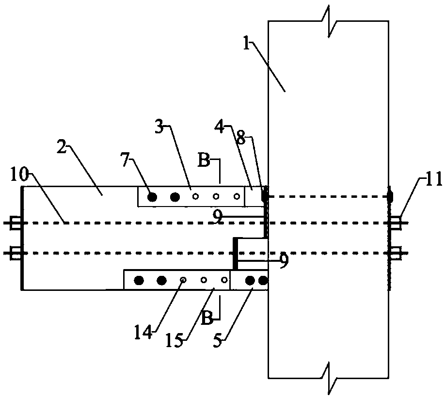
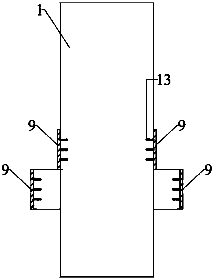
[0038] like figure 1 As shown, in the self-resetting prefabricated concrete beam-column node device of the top and bottom frictional energy dissipation of the present invention, the main component includes a precast concrete column 1, a precast concrete beam 2, and the connecting components include the upper and lower frictional energy dissipation devices of the node and the anti-local compression Embedded steel plates 9 at the ends of bad beams and columns. Under earthquake action, the prestressed tendons 10 in the self-resetting precast concrete beam-column joints can provide self-resetting force to eliminate the residual deformation of the joints, and the frictional energy dissipation devices arranged at the beam-column joints can consume a large amount of seismic energy, avoiding the The main structural components such as columns have o...


PUM


Abstract

The invention discloses a self-restoring precast concrete beam-column joint device with top and bottom friction energy dissipation. The beam-column joint device comprises an upper friction energy dissipation device and a lower friction energy dissipation device. Two inner friction steel plates with bolt holes in the upper friction energy dissipation device are welded to an end plate to form a whole, and then the end plate is fixed to a column through tensile bolts; two corresponding outer friction steel plates are fixed to a precast concrete beam through shear bolts. Two outer friction steel plates with bolt holes are arranged at the lower end of a joint and fixed to the precast concrete beam through shear bolts, and two inner friction steel plates corresponding to the outer friction steelplates are fixed to a hidden bracket of the precast concrete column through shear bolts. Friction plates are arranged between the outer friction steel plates and the inner friction steel plates. Friction-type high-strength bolts penetrate through the outer friction steel plates, the friction plates, the inner friction steel plates and the precast concrete beam to connect all components at the upper end and the lower end together.

Description

technical field [0001] The invention belongs to the field of civil engineering and relates to a self-resetting prefabricated concrete beam-column node device for top-bottom frictional energy consumption. Background technique [0002] Earthquakes bring extremely serious disasters to human beings. The traditional seismic design adopts the ductility design method, that is, under the action of an earthquake, some structural components yield and fail in advance, but the overall function will not be lost, and most of the seismic energy is dissipated by the plastic deformation of the components after yielding, so as to achieve The purpose of ensuring the safety of the main structure. Although this traditional design method based on bearing capacity has certain reliability in avoiding building damage and even collapse causing casualties, it cannot effectively control the economic damage caused by earthquakes in moderate or strong earthquakes. After most major earthquakes, although...

Claims


Application Information

Patent Timeline
IPC IPC(8): E04B1/21E04B1/98E04H9/02
CPCE04B1/21E04B1/215E04H9/021
Inventor 周臻黄林杰田会文司怡章梦霞
Owner SOUTHEAST UNIV
Why Eureka
Eureka Blog
Learn More