Connecting device capable of reducing stress of heating pipes of roasting furnace

A connecting device and heating tube technology, which is applied in the direction of pipes/pipe joints/fittings, pipe elements, siphons, etc., can solve the problems of welding seam tearing of heating pipes, affecting heating pipes, bursting pipes, etc., so as to reduce the stress, Easy to use and avoid tearing effect

Active Publication Date: 2018-10-19
HENAN JUNHUA DEV
View PDF4 Cites 2 Cited by
  • Summary
  • Abstract
  • Description
  • Claims
  • Application Information

AI Technical Summary

Problems solved by technology

[0002] The steam calciner is an important equipment for the production of soda ash. The steam calciner is composed of a feed screw, a furnace head part, a furnace body part, a steam inlet shaft and a transmission device. High-temperature steam is introduced into the furnace body through the steam inlet shaft. Let the materials entering the furnace head and furnace body from the feed port react to produce soda ash, and then the finished product of soda ash is discharged through the furnace head, and the transmission device plays the role of rotating the furnace body, but the current calciner is unstable and may vibrate It will affect the heating tube and cause problems with the heating tube
[0003] There is a problem in the existing heating tube connection method of the calciner. The two sections of the heating tube in each layer are connected by an annular tube. At the same time, a horseshoe-shaped joint is separated from the lower layer to connect the annular tube of the heating tube in the upper layer. The stress at the horseshoe-shaped interface of the heating tube is large. , often cause the welding seam of the heating tube to tear, burst the tube, and affect the operation of the calciner. Therefore, we propose a connection device that reduces the stress of the heating tube of the calciner to solve the above problems

Method used


Image

  • Connecting device capable of reducing stress of heating pipes of roasting furnace
  • Connecting device capable of reducing stress of heating pipes of roasting furnace
  • Connecting device capable of reducing stress of heating pipes of roasting furnace

Examples


Embodiment Construction

[0021] The following will clearly and completely describe the technical solutions in the embodiments of the present invention with reference to the accompanying drawings in the embodiments of the present invention. Obviously, the described embodiments are only some, not all, embodiments of the present invention.

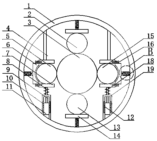
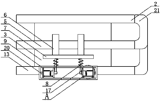
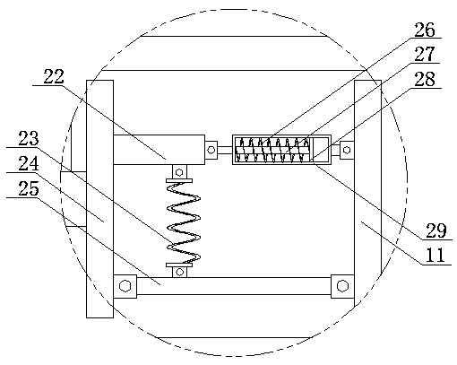
[0022] refer to Figure 1-4 , a connection device for reducing the stress of the heating tube of the calciner, comprising an outer furnace tube 1, an inner furnace tube 3 is arranged inside the outer furnace tube 1, and a first heating tube 2 and a second heating tube are respectively arranged around the inner furnace tube 3 5. The third heating pipe 13 and the fourth heating pipe 15, the first heating pipe 2 and the second heating pipe 5, the third heating pipe 13 and the fourth heating pipe 15 are all connected by an arc-shaped elbow 21, and the arc-shaped elbow 21 can reduce the stress concentration of each heating tube, and one end of the first heating tube 2 and...


PUM


Abstract

The invention discloses a connecting device capable of reducing stress of heating pipes of a roasting furnace. The device comprises an outer furnace barrel in which an inner furnace barrel is arranged, wherein a first heating pipe, a second heating pipe, a third heating pipe and a fourth heating pipe are correspondingly arranged around the inner furnace barrel and are all connected through arc-shaped bends; one end of the first heating pipe and one end of the third heating pipe are provided with positioning plates; a damping device is arranged at one end of each positioning plate; two fixing rods are fixed to the sidewall of one inner end of the outer furnace barrel; and a mounting plate is fixed to the lower end of each fixing rod. According to the device, the problem that two sections ofexisting heating pipes at each layer are connected through an annular pipe which leads to high stress can be solved; the arc-shaped bends are used for connecting, so that the stress applied to the heating pipes of the roasting furnace is reduced, and welding seams of the heating pipes are prevented from tearing, and as a result, the running time of the heating pipes of the roasting furnace can beincreased; and the convenience of use is ensured.

Description

technical field [0001] The invention relates to the technical field of combined soda ash, in particular to a connection device for reducing the stress of a heating tube of a calciner. Background technique [0002] The steam calciner is an important equipment for the production of soda ash. The steam calciner is composed of a feed screw, a furnace head part, a furnace body part, a steam inlet shaft and a transmission device. High-temperature steam is introduced into the furnace body through the steam inlet shaft. Let the materials entering the furnace head and furnace body from the feed port react to produce soda ash, and then the finished product of soda ash is discharged through the furnace head, and the transmission device plays the role of rotating the furnace body, but the current calciner is unstable and may vibrate It will affect the heating tube and cause problems with the heating tube. [0003] There is a problem in the existing heating tube connection method of the...

Claims


Application Information

Patent Timeline
Patent Type & Authority Applications(China)
IPC IPC(8): F16L43/00F16L3/04F16L57/00F16F15/08C01D7/00
CPCF16F15/046F16F15/08F16L3/04F16L43/00F16L57/00C01D7/00
Inventor 甘世杰高卫星邓占听冯步天王伟王振
Owner HENAN JUNHUA DEV
Why Eureka
Try Eureka