Method and device for detecting angular acceleration of rotator

An angular acceleration and rotating body technology, which is applied in the direction of measuring acceleration, devices using optical methods, measuring devices, etc., can solve the problem of inability to accurately read the angular acceleration, and achieve the effect of simple and effective measurement and calculation analysis methods.

Active Publication Date: 2018-10-19
BEIJING INSTITUTE OF TECHNOLOGYGY
View PDF12 Cites 20 Cited by
  • Summary
  • Abstract
  • Description
  • Claims
  • Application Information

AI Technical Summary

Problems solved by technology

[0004] At present, researchers have used the Laguerre-Gaussian beam with vortex phase to detect the angular velocity of the rotating body. However, when the rotating body is subjected to torque, it has angular acceleration. When the rotating body rotates at a non-uniform speed, the frequency of the vortex beam will vary with the The time changes, and only the Fourier transform of the beat frequency signal cannot accurately read the angular acceleration

Method used


Image

  • Method and device for detecting angular acceleration of rotator
  • Method and device for detecting angular acceleration of rotator
  • Method and device for detecting angular acceleration of rotator

Examples


Embodiment 1

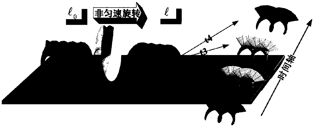
[0075] Embodiment 1: A double-mode multiplexed Laguerre-Gaussian beam with opposite angular quantum numbers realizes the detection of the angular velocity of a rotating body.

[0076] In this embodiment and the following four embodiments, the ω of the Laguerre-Gaussian beam 0 The values ​​are all 1.5mm.

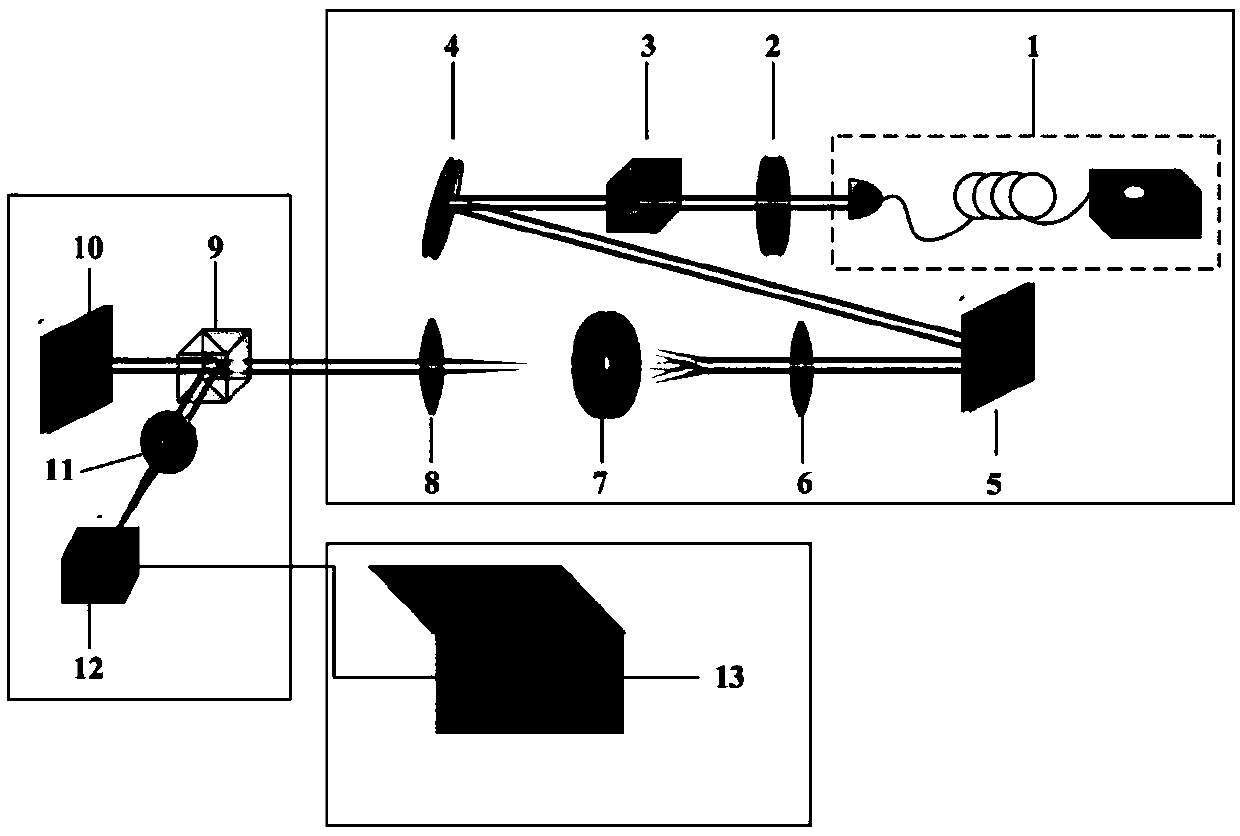
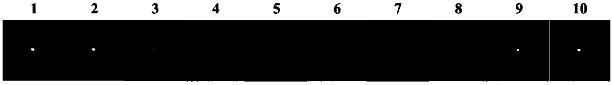
[0077] by giving image 3 The liquid crystal spatial light modulator 5 in the shown device is loaded with a holographic grating to realize the generation of different dual-mode multiplexed Laguerre-Gaussian beams with opposite angular quantum numbers, which are used as detection beams. And use the liquid crystal spatial light modulator 10 to load a dynamic hologram for simulating the rotation of the rotating body, the light field distribution detected by the infrared camera 12 is as follows: Figure 4 shown. Figure 5 (a) Given that for a uniformly rotating turntable, the rotational speed is 6.28×10 -3 rad / s. When the dual-mode Laguerre-Gaussian beam of ±25 is incident, ...

Embodiment 2

[0078] Embodiment 2: The dual-mode multiplexed Laguerre-Gaussian beam with opposite angular quantum numbers realizes the detection of the angular acceleration of a rotating body.

[0079] pass image 3 The liquid crystal spatial light modulator 10 in the device shown is loaded with a dynamic holographic grating, simulating a uniformly accelerated rotating body, with an initial velocity Ω 0 (t)=3.14×10 -3 rad / s, angular acceleration a(t)=3.93×10 -5 rad / s 2 . Image 6 (a) When the dual-mode Laguerre-Gaussian beam of ±25 is incident, the time-domain signal of the beat frequency signal is measured, and the signal is analyzed by Fourier transform, and the spectrum data is obtained as Image 6 (b), from the spectrogram, only the rotational speed value range of the rotating body within a period of time can be read, but the acceleration information cannot be read.

Embodiment 3

[0080] Embodiment 3: Time-frequency analysis is performed on the beat frequency signal by using the short-time Fourier transform method.

[0081] Perform time-frequency analysis on the non-stationary beat frequency signal corresponding to the measured non-uniform acceleration. Here we use the short-time Fourier transform method to process the beat frequency signal. The short-time Fourier transform is related to Fourier A transformation of , which can calculate the law of frequency change with time. Figure 8 It is the time-domain diagram and short-time Fourier transform diagram of the detection of a uniformly accelerating rotating body by using ±25-order multiplexed vortex beams. In the short-time Fourier transform diagram, the slope is df / dt=3.125×10 -4 Hz / s. Therefore, according to the formula Reverse the acceleration of the rotating body a(t) = 3.93×10 -5 rad / s 2 , consistent with the actually set rotating body acceleration.


PUM


Abstract

The invention discloses a method and device for detecting the angular acceleration of a rotator. In the method, a dual-mode multiplexed Laguerre-Gaussian beam having an opposite angular quantum numberis used as a detecting beam. The frequency of scattered light is modulated because of a rotational Doppler effect when the dual-mode multiplexed Laguerre-Gaussian beam irradiates the rotator along anaxis of rotation. By using a coherent detection method, the central light intensity of the interference spot is detected and recorded. The time-varying rule df / dt of the frequency of the central light intensity and the angular acceleration a(t)of the rotator satisfies a direct proportion relationship, namely a(t)=([pi] / l)(df / dt), wherein l is the orbital angular quantum number of the detecting beam. By using the short-time Fourier transform method, the change of the central light intensity of the interference spot is subjected to time-frequency analysis, the time-varying rule of the frequencyof an intensity signal can be obtained, and then the angular acceleration of the rotator is further deduced. The device is simple in system structure and easy to operate, can measure the angular velocity and the angular acceleration of the rotator in real time, and has great progress compared with the prior art.

Description

technical field [0001] The invention relates to the field of optoelectronic technology, in particular to a method and device for detecting the angular acceleration of a rotating body Background technique [0002] The vortex beam is a new type of beam, which has a spiral wavefront structure. The beam center of the vortex beam has a phase singularity, so that the cross-sectional light intensity is distributed in a ring-shaped hollow. In 1992, Allen et al found that the complex amplitude expression of the vortex beam contains Among them, l is the angular quantum number, also known as the topological kernel number, is the angular coordinate (L. Allen et al., Physical Review A, Volume 45, 1992, p. 8145). The angular quantum number l is the eigenvalue of the orbital angular momentum (OAM) carried by the vortex beam, and each photon in the vortex beam carries Orbital angular momentum ( To reduce the Planck constant), common vortex beams include Laguerre-Gaussian beams, Bess...

Claims


Application Information

Patent Timeline
Patent Type & Authority Applications(China)
IPC IPC(8): G01P15/16G01P3/36
CPCG01P3/36G01P15/16
Inventor 高春清翟焱望付时尧
Owner BEIJING INSTITUTE OF TECHNOLOGYGY
Why Eureka
Try Eureka