Robot And Gear Unit
一种机器人、外齿轮的技术,应用在发动机元件、带有齿的元件、齿轮润滑/冷却等方向,能够解决难以提高润滑性能等问题
- Summary
- Abstract
- Description
- Claims
- Application Information
AI Technical Summary
Problems solved by technology
Method used
Image

Examples
no. 1 approach
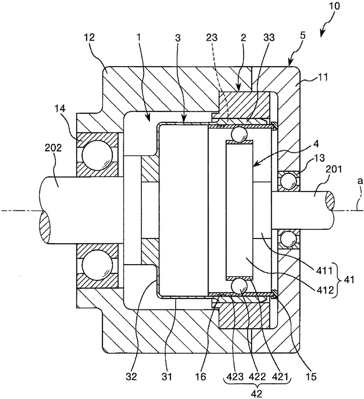
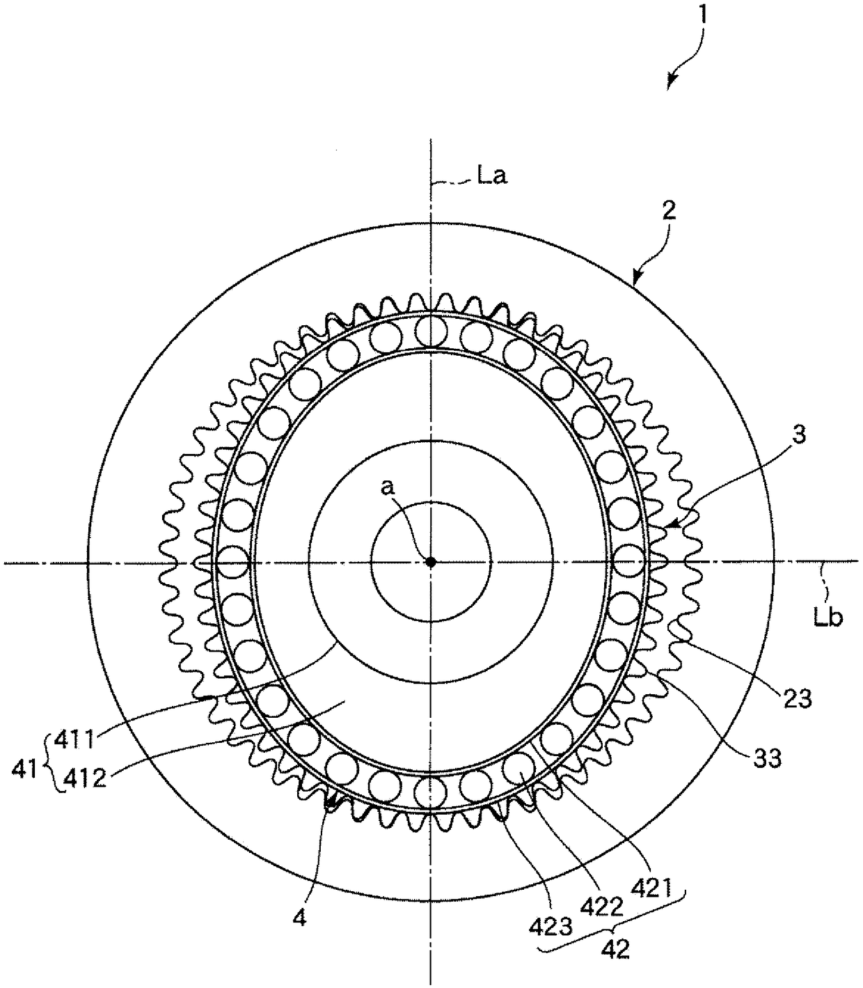
[0054] figure 2 It is a longitudinal sectional view showing the gear unit according to the first embodiment of the present invention. image 3 yes figure 2 Front view of the gear unit with the gear unit shown. Figure 4 is for illustration figure 2 It is a partially enlarged longitudinal sectional view of the first and second sealing members included in the gear unit shown. Figure 5 yes Figure 4 A perspective view of the first sealing component is shown. Image 6 yes Figure 4 A perspective view of the second sealing component is shown. It should be noted that, in each figure, for convenience of description, the size of each part is appropriately exaggerated for illustration as needed, and the size ratio between each part does not necessarily coincide with the actual size ratio. In addition, in image 3 In FIG. 2 , illustration of a first sealing member 15 and a second sealing member 16 to be described later is omitted for convenience of description. It should be...
no. 2 approach
[0092] Next, a second embodiment of the present invention will be described.
[0093] Figure 7 It is a partially enlarged longitudinal sectional view for explaining the first and second seal members included in the gear unit according to the second embodiment of the present invention.
[0094] This embodiment is the same as the above-mentioned first embodiment except that the configurations of the first sealing member and the second sealing member are different. In addition, in the following description, regarding this embodiment, it demonstrates centering on the difference from the said embodiment, and omits description about the same matter. In addition, in Figure 7 In , the same symbols are assigned to the same configurations as those in the above-mentioned embodiment.
[0095] Figure 7 The illustrated gear unit 10A has a gear unit 1A and a case 5 that accommodates the gear unit 1A. The gear unit 1A has a rigid gear 2 as an internal gear, a flexible gear 3A as an ex...
no. 3 approach
[0103] Next, a third embodiment of the present invention will be described.
[0104] Figure 8 It is a longitudinal sectional view showing the gear unit according to the third embodiment of the present invention.
[0105] This embodiment is the same as the above-mentioned first embodiment except that the configuration of the external gear is different. In addition, in the following description, regarding this embodiment, it demonstrates centering on the difference from the said embodiment, and omits description about the same thing. In addition, in Figure 8 In , the same symbols are assigned to the same configurations as those in the above-mentioned embodiment.
[0106] Figure 8 The gear unit 10B shown has a gear unit 1B and a cover 11 . The gear unit 1B has a flexible gear 3B as a hat-shaped external gear disposed inside the rigid gear 2 . The flexible gear 3B has a flange portion 32B (connection portion) that is connected to one end portion of the cylindrical trunk p...
PUM
 Abstract
Description
Claims
Application Information
 - R&D
- Intellectual Property
- Life Sciences
- Materials
- Tech Scout
- Unparalleled Data Quality
- Higher Quality Content
- 60% Fewer Hallucinations
Browse by: Latest US Patents, China's latest patents, Technical Efficacy Thesaurus, Application Domain, Technology Topic, Popular Technical Reports.
© 2025 PatSnap. All rights reserved.Legal|Privacy policy|Modern Slavery Act Transparency Statement|Sitemap|About US| Contact US: help@patsnap.com