Continuous shunting feeding mechanism

The technology of a feeding mechanism and a feeding mechanism is applied in the field of continuous shunt feeding mechanism, which can solve the problems of low efficiency of workpiece shunt feeding, poor accuracy of workpiece shunt feeding, and high degree of equipment loss, and achieve fast and convenient The effect of translational reset and reasonable structure design

Inactive Publication Date: 2018-10-23
沈洁
View PDF0 Cites 8 Cited by
  • Summary
  • Abstract
  • Description
  • Claims
  • Application Information

AI Technical Summary

Problems solved by technology

The existing split feeding mechanism can only evenly divide the workpieces on the front transmission mechanism to two rear transmission mechanisms for transmission separately, and it is difficult to realize the even distribution of workpieces on the front transmission mechanism to multiple rear transmission mechanisms for transmission separately, and The existing split feeding mechanism can only grab the workpieces on the front transfer mechanism one by one and transfer them to the rear transfer mechanism for split transfer, which makes the split feeding efficiency of the workpieces low, and because the workpiece grabbing mechanism requires high Frequent and continuous reciprocating actions, the equipment loss is relatively high, and the existing workpiece branch feeding mechanism is difficult to accurately transfer multiple workpieces to multiple post-transfer mechanisms in the process of split feeding the workpiece. The workpiece can continue to be conveyed and processed, and the accuracy of the workpiece split feeding is poor, so it is difficult to meet the needs of the workpiece split feeding

Method used


Image

  • Continuous shunting feeding mechanism
  • Continuous shunting feeding mechanism
  • Continuous shunting feeding mechanism

Examples


Embodiment Construction

[0016] In order to further describe the present invention, a specific implementation of a continuous branch feeding mechanism will be further described below in conjunction with the accompanying drawings. The following examples are explanations of the present invention and the present invention is not limited to the following examples.

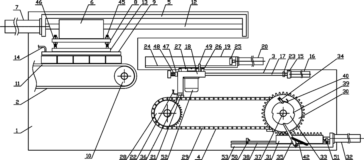
[0017] Such as figure 1 As shown, a continuous branch feeding mechanism of the present invention includes a feeding bracket 1, a feeding mechanism 2, a pushing mechanism 3 and an intermittent driving mechanism 4, and the feeding mechanism 2 is horizontally arranged on the side above the feeding bracket 1, Pushing mechanism 3 is horizontally and fixedly arranged on the feeding bracket 1 on one side of feeding mechanism 2 , and intermittent driving mechanism 4 is horizontally arranged on feeding bracket 1 on the lower side of pushing mechanism 3 . The feeding mechanism 2 of the present invention includes an upper translation support 5, a feeding...


PUM


Abstract

The invention discloses a continuous shunting feeding mechanism, and belongs to the field of workpiece conveying mechanical equipment. A material pushing mechanism is horizontally and fixedly arrangedon the feeding bracket at one side of the feeding mechanism, an intermittent driving mechanism is horizontally arranged on the feeding bracket at the lower side of the material pushing mechanism, a material suction electromagnet is horizontally and fixedly arranged on the lower side of a connecting guide plate, a rotating base is rotatably connected to middle of the lower side of a material bearing bracket, a material pushing cylinder is horizontally and fixedly arranged on one side of the material bearing bracket, two adsorption armatures are uniformly and fixedly arranged on the outer sideof a feeding chain, a feeding rotating shaft on one side of a feeding ratchet wheel is vertically and rotatably connected with a feeding gear, the feeding gear is connected with the upper side of a translation rack in a meshing mode, and a plurality of the conveying guide belts on the upper side of the feeding bracket are perpendicular to feeding guide rods. The continuous shunting feeding mechanism has reasonable structural design, can carry out translational feeding on a plurality of workpieces as a whole, and can carry out shunting feeding and conveying on the fed workpieces one by one in an orderly manner to meet the requirements of machining and use.

Description

technical field [0001] The invention belongs to the field of workpiece conveying machinery and equipment, and in particular relates to a continuous branch feeding mechanism, which is mainly used in the field of continuous branch feeding, conveying and processing of workpieces. Background technique [0002] The mechanical workpiece is a single piece that makes up the machine and its inseparability. It plays an important role in the automation industry. The mechanical workpiece includes the connection of parts, the supporting parts, the lubricating lubrication system and the sealing Parts, parts of the transmission system that transmit motion and energy. In the process of producing and processing mechanical workpieces, the workpieces need to undergo processing steps such as die-casting, grinding, milling and drilling in sequence. The existing workpieces are processed Generally, the production line is used to carry out the above-mentioned processing sequentially during the hori...

Claims


Application Information

Patent Timeline
IPC IPC(8): B65G25/04
CPCB65G25/04
Inventor 沈洁
Owner 沈洁
Why Eureka
Try Eureka