Micro-inertial measuring component structure to resist high overload

A technology of micro-inertial measurement and component structure, which is applied in directions such as navigation through velocity/acceleration measurement, can solve problems such as rigid displacement, uneven potting and filling, and wiring detached from pads, etc., to reduce assembly complexity, Improving the reliability of fixed connection and satisfying the effect of miniaturization design

Pending Publication Date: 2018-10-23
SUZHOU R&D CENT OF NO 214 RES INST OF CHINA NORTH IND GRP
View PDF11 Cites 6 Cited by
  • Summary
  • Abstract
  • Description
  • Claims
  • Application Information

AI Technical Summary

Problems solved by technology

However, such designs usually have problems such as low reliability of electrical connections between sensor circuit boards, difficult assembly, and low assembly accuracy.
Because the electrical connection of this type of design is in the form of soldered wires, it is easy to cause the wires to be exposed outside the support structure or redundantly wound inside the support structure
The wiring is exposed to the outside of the structure, and it is easy to cause the wiring to detach from the pad during the process of overload impact. During the potting process, because the potting material will release a large amount of stress when it solidifies, the wiring will be broken or detached from the solder due to the stress. plate
However, if the wiring is placed inside the assembly support structure, due to the large number of electrical connections of the micro-inertial measurement component, it may hinder the flow path of the potting material, resulting in uneven potting and filling, large stress, and high overload. rigid displacement
Moreover, the internal space of micro-inertial measurement components is usually small. The traditional assembly method and the overall assembly of welding connection components bring great inconvenience, poor maintainability, and greatly reduce the development efficiency of components.

Method used


Image

  • Micro-inertial measuring component structure to resist high overload
  • Micro-inertial measuring component structure to resist high overload
  • Micro-inertial measuring component structure to resist high overload

Examples


Embodiment Construction

[0027] The present invention will be further described below in conjunction with the accompanying drawings. The following examples are only used to illustrate the technical solution of the present invention more clearly, but not to limit the protection scope of the present invention.

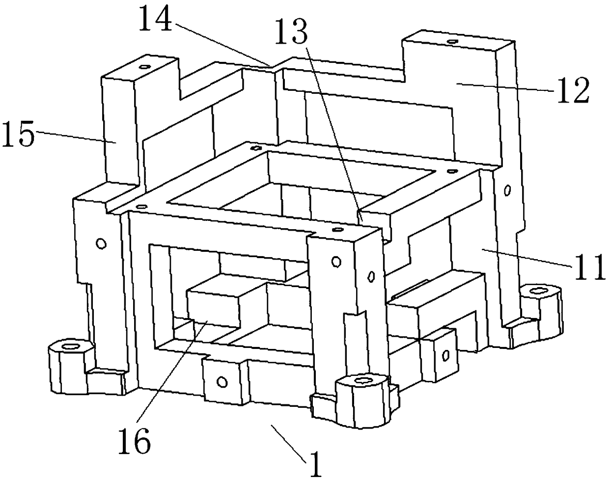
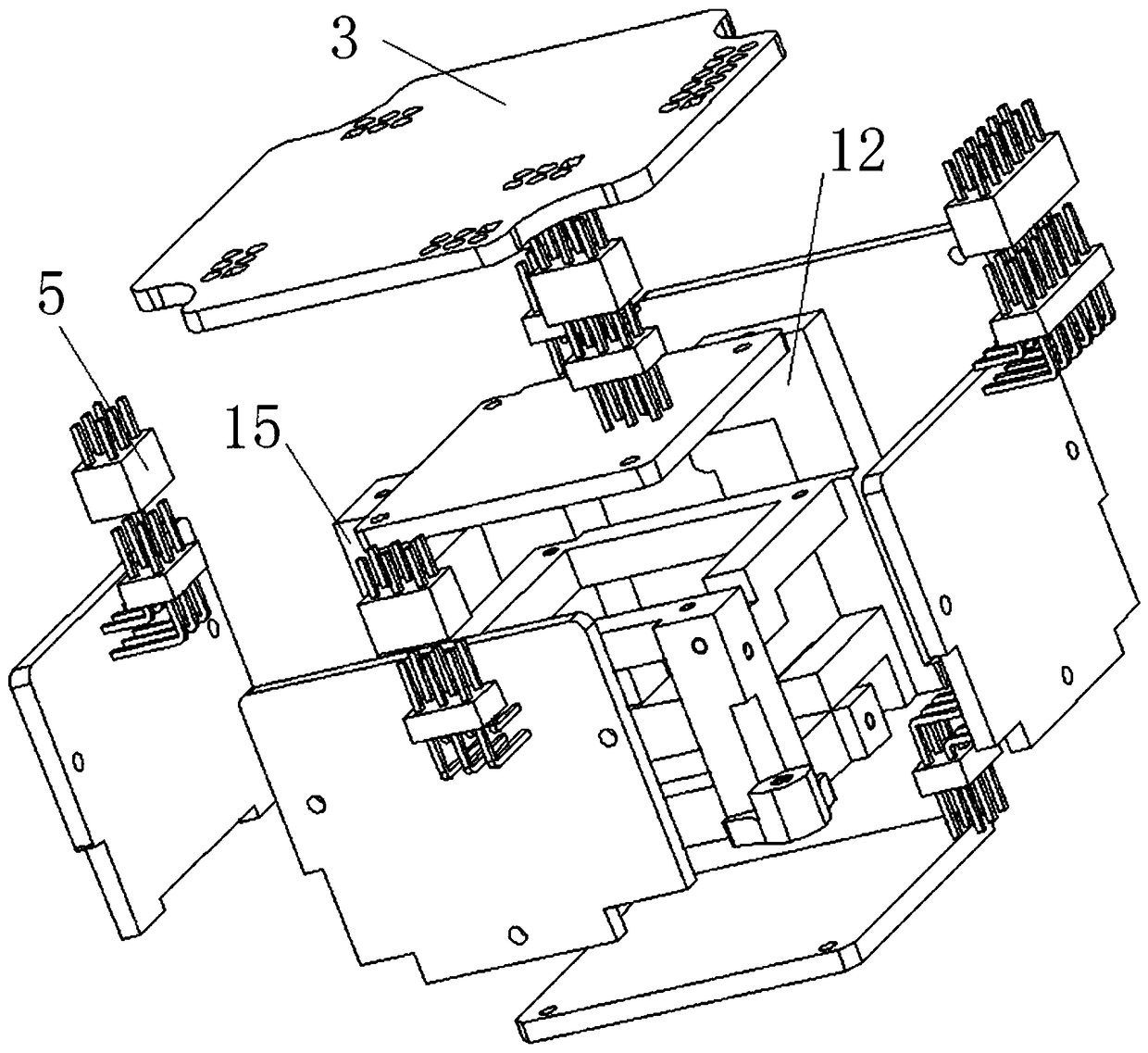
[0028] Such as figure 1 , figure 2 As shown, in this patent, the anti-overload support structure 1 of the micro-inertial measurement component is designed as a hollow structure in the middle of an approximate hexahedron, and three orthogonal axial sides 11 are used for penetration treatment, and a boss 12 design is added to the top plane, so the structure has a total of 7 flat surfaces for mounting circuit boards. Among them, six mutually orthogonal hollow planes are used to install MEMS inertial sensor circuit board 2, the boss 12 on the top can be used to install core controller circuit board 3, and the space inside the frame is filled with potting material to protect electronic devices. S...


PUM


Abstract

The invention discloses a micro-inertial measuring component structure to resist a high overload, and the micro-inertial measuring component structure comprises a supporting structure that is a hollowed-out hexahedral structure formed by supporting ribs. Three orthogonal axial sides of the hexahedral structure are open-through. At least one frame of one hollow plane extends outwardly to form a lugboss, so that the supporting structure has seven hollow planes for mounting circuit boards. A potting material is filled into the internal space of the hexahedral structure through the three orthogonal axial sides. The micro-intertial measuring component structure reduces the degree of assembly complexity of a sensor circuit board as well as an overall component, and reserves a space or a passagefor flowing of the material in the potting process to ensure the compactness of the potting. The micro-inertial measuring component structure is novel in design and easy for assembly operation, and high overload requirements can be met while realization of miniaturization.

Description

technical field [0001] The invention belongs to the field of mechanical design, and mainly relates to the anti-overload structure design and mechanical assembly scheme of a micro-inertial measurement component. Background technique [0002] Micro-inertial measurement components are inertial measurement components based on MEMS gyroscopes and MEMS accelerometers, which are often used in inertial navigation or integrated navigation systems. Its working principle is to use the micro-inertial sensor (MEMS gyroscope and MEMS accelerometer) to establish a space inertial measurement coordinate system, that is, to measure the angular velocity through the MEMS gyroscope, and to measure the acceleration with the MEMS accelerometer, to obtain the dynamic parameters of the moving carrier, and then through integration and navigation The algorithm calculates the posture information of the moving carrier. At present, monolithic three-axis MEMS gyroscopes and three-axis MEMS accelerometers...

Claims


Application Information

Patent Timeline
Patent Type & Authority Applications(China)
IPC IPC(8): G01C21/16
CPCG01C21/16
Inventor 鞠莉娜蒋鹏高玉霞刘海亮
Owner SUZHOU R&D CENT OF NO 214 RES INST OF CHINA NORTH IND GRP
Why Eureka
Try Eureka