
Machining device for fittings

A technology for processing devices and accessories, applied in the field of mechanical parts processing, can solve problems such as low drilling efficiency, and achieve the effects of improving speed and efficiency, increasing contact area, and stabilizing the center of gravity

Pending Publication Date: 2018-10-26
重庆炅达贸易有限公司
View PDF0 Cites 5 Cited by
  • Summary
  • Abstract
  • Description
  • Claims
  • Application Information

AI Technical Summary

Problems solved by technology

Therefore, can only carry out drilling one by one to concave-shaped parts at present, and the efficiency of drilling is relatively low, lacks the device that carries out batch drilling to concave-shaped parts at present

Method used


Image

  • Machining device for fittings
  • Machining device for fittings
  • Machining device for fittings

Examples


Embodiment Construction

[0020] The following is further described in detail through specific implementation methods:

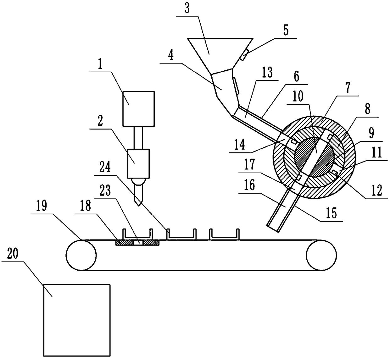
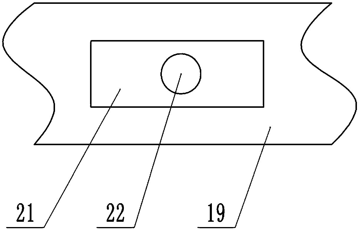
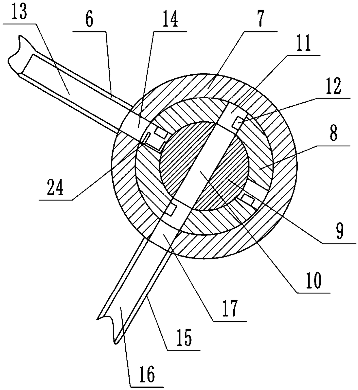
[0021] The reference signs in the drawings of the description include: cylinder 1, drilling motor 2, feed hopper 3, through pipe 4, vibrator 5, feed pipe 6, fixed ring 7, rotating ring 8, fixed plate 9, first Pass trough 10, second pass trough 11, block 12, feed channel 13, feed port 14, discharge pipe 15, discharge channel 16, discharge port 17, support platform 18, conveyor belt 19, collection box 20, Place the groove 21, the first through hole 22, the second through hole 23, and the concave-shaped part 24.

[0022] The embodiment is basically as attached Figure 1-Figure 7 Shown: a processing device for accessories, including a frame, on which a cylinder 1 is installed through screws, the cylinder rod of the cylinder 1 is vertically arranged, and a drilling motor 2 is installed on the bottom end of the cylinder rod through screws, and the drill The output shaft of the hole motor...


PUM


Abstract

The invention relates to the field of machining of mechanical parts, in particular to a machining device for fittings. The machining device comprises a rack, the rack is vertically and slidably connected with a drill bit, and the rack is provided with a straightening mechanism. The straightening mechanism communicates with a feeding hopper and communicates with a discharging pipe, an intermittently-conveying conveyer belt is arranged below the discharging end of the discharging pipe, the belt face of the conveyer belt is provided with a plurality of placement grooves, and the placement groovesare internally provided with first through holes. A supporting table located below the drill bit is arranged under the conveyer belt in an attached manner, the supporting table is provided with a second through hole, and the supporting table is connected with an electromagnet. By means of the machining device for the fittings, batched drilling of the U-shaped parts is realized.

Description

technical field [0001] The invention relates to the field of machining of mechanical parts, in particular to a processing device for accessories. Background technique [0002] Accessories refer to the parts or components of the assembly machinery, and also refer to the parts or components that are reinstalled after damage. There are various types of accessories, ranging from engines, fuel tanks, etc., to bolts, washers, etc. Moreover, the shapes of accessories are also different, such as I-shaped parts, concave-shaped parts, shaft parts and square parts, etc. [0003] Wherein, during the processing of the concave-shaped parts, holes need to be drilled on the bottom surface of the concave-shaped parts, so as to facilitate the assembly and assembly of the concave-shaped parts by bolts or screws. Due to the specificity of the shape of the concave-shaped parts, the drilling on the concave-shaped parts is usually completed one by one, that is, the concave-shaped parts are place...

Claims


Application Information

Patent Timeline
Patent Type & Authority Applications(China)
IPC IPC(8): B23Q7/00B23Q7/18B23Q3/154B23B39/00
CPCB23B39/00B23Q3/1543B23Q7/00B23Q7/003B23Q7/18
Inventor 姚竹清
Owner 重庆炅达贸易有限公司
Learn More