Multi-parallel coexisting-cooperative-cognitive robot large-scale optical mirror surface machining device

A technology of optical mirror surface and processing equipment, applied in metal processing equipment, optical surface grinder, grinding/polishing equipment, etc., can solve the problems of damage to optical mirror surface, slow dynamic response speed, difficult to control, etc., to ensure optical characteristics and performance, improve the mirror processing accuracy, not easy to deform or damage the effect

Active Publication Date: 2018-10-26
CHINA UNIV OF MINING & TECH
View PDF6 Cites 7 Cited by
  • Summary
  • Abstract
  • Description
  • Claims
  • Application Information

AI Technical Summary

Problems solved by technology

[0003] The current traditional mirror surface processing equipment usually uses a single series mechanism to process the mirror surface. The series mechanism has the disadvantages of small rigidity, low precision, slow dynamic response speed, and large cumulative error.
The structure of this kind of mirror processing equipment is relatively complicated and difficult to control, and in the processing of large-scale curved optical mirrors with special purposes such as high-order curved surfaces, sinusoidal curved surfaces, and free-form surfaces, the number of repetitions of "surface shape measurement-polishing processing" increases. , there are problems such as low processing efficiency, damage to the optical mirror surface during processing, and affecting t

Method used


Image

  • Multi-parallel coexisting-cooperative-cognitive robot large-scale optical mirror surface machining device
  • Multi-parallel coexisting-cooperative-cognitive robot large-scale optical mirror surface machining device
  • Multi-parallel coexisting-cooperative-cognitive robot large-scale optical mirror surface machining device

Examples


Embodiment Construction

[0031] The present invention will be described in detail below in conjunction with the accompanying drawings. Among them, the moving pair P in UPS stands for active moving pair, the moving pair P of UPU stands for passive moving pair, the moving pair P in PUU stands for active moving pair; U stands for Hooke hinge, P stands for lead screw, and S stands for ball hinge.

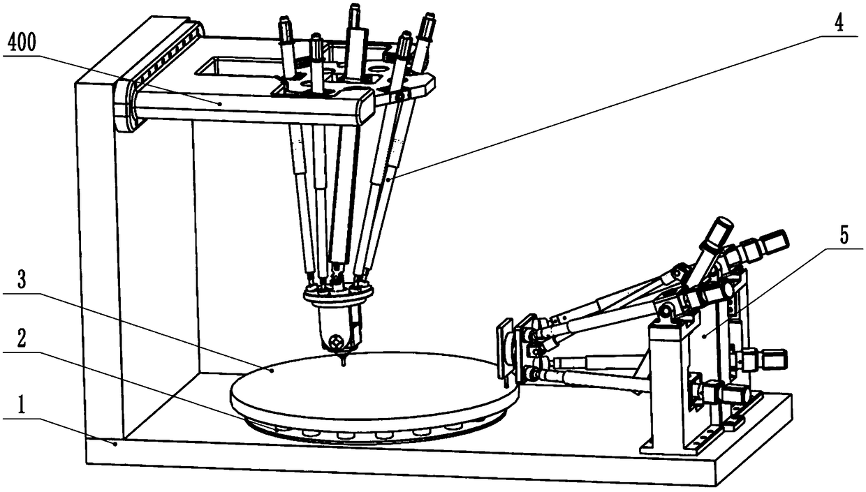
[0032] Such as Figure 1 to Figure 4 As shown, a large-scale optical mirror processing equipment of a multi-parallel co-integration robot includes a processing unit, a large mirror support unit, and a mirror rotation fixing unit 2. The processing unit includes a processing tool unit and a processing tool during optical mirror processing. A drive mechanism that provides the required path, processing force and processing attitude; the large mirror support unit includes an L-shaped support frame 1, and the mirror rotation and fixing unit 2 is arranged on the upper end of the horizontal platform of the L-shaped sup...


PUM


Abstract

The invention discloses a multi-parallel coexisting-cooperative-cognitive robot large-scale optical mirror surface machining device. The machining device is characterized in that an L-shaped supporting frame is used for fixing and supporting two different parallel machining robots and a to-be-machined mirror surface, a mirror surface inner ring machining unit 4 is a 5 UPS + UPU type parallel machining robot, a mirror surface outer ring machining unit is a 4 UPS + PUU type parallel machining robot, an active partitioning flexible hydraulic supporting system is installed on a mirror surface rotary fixing unit, the supporting system serves as a flexible support of the to-be-machined mirror surface in the machining process, the output force of each supporting point is adjusted, and the opticalmirror surface is balanced in stress in the machining process. The machining device is small in size, high in rigidity, small in accumulative error, high in machining precision and capable of improving the machining efficiency of the optical mirror surface; and meanwhile, the rigid supporting system is improved, the output force of each supporting point can be adjusted, so that the optical mirrorsurface is balanced in stress in the machining process, and is not prone to be deformed or damaged, and the machining device is more suitable for machining complex curved surface optical mirror surfaces.

Description

technical field [0001] The invention relates to an optical mirror processing equipment, in particular to a multi-parallel fusion robot large-scale optical mirror processing equipment, which belongs to the technical field of precision component processing equipment. Background technique [0002] With the rapid development of optical technology, curved optical parts as the core components are widely used in military reconnaissance, aerospace and many civilian fields, such as projectors and camera lenses, viewfinders, telescopes and other fields, and modern optical systems It is rapidly developing in the direction of large diameter, high precision, high resolution and high power, and the demand for large optical mirrors is increasing, so there is a higher standard for the processing accuracy of optical mirrors. The processing process of optical mirror mainly includes blank processing, rough grinding, grinding, polishing and other processes. Among them, the grinding and polishin...

Claims


Application Information

Patent Timeline
IPC IPC(8): B24B13/00B24B13/01B24B41/06
CPCB24B13/00B24B13/01B24B41/06
Inventor 程刚孔一璇万勇建张慧珍郭锋陈世彪金祖进徐世昌
Owner CHINA UNIV OF MINING & TECH
Why Eureka
Try Eureka