
Magnetic suspension device and micropositioner

A maglev, magnetic steel technology, applied in transportation and packaging, electrical components, semiconductor/solid-state device manufacturing, etc., can solve the problems of aerodynamic hysteresis, difficult flexible mechanism, temperature rise, etc., to achieve high motion performance requirements, improve vertical The effect of performance and simple production process

Pending Publication Date: 2021-12-03
YINGUAN SEMICON TECH CO LTD
View PDF1 Cites 0 Cited by
  • Summary
  • Abstract
  • Description
  • Claims
  • Application Information

AI Technical Summary

Problems solved by technology

Generally, the vertical actuator of the micro-motion stage usually adopts a combination scheme of a zero-stiffness gravity compensation device and a voice coil motor. The zero-stiffness gravity compensation device is used to compensate the gravity of the stage device in the micro-motion stage, and the stage device is used to place silicon chips. , and drives the silicon wafer to move, and the voice coil motor provides the elastic force of the flexible mechanism and the push-pull force required for the vertical movement of the stage device. Since the stiffness of the flexible mechanism has a linear region and a nonlinear region in different vertical travel ranges, so Simply controlling the push-pull force of the voice coil motor is difficult to completely compensate the elastic force of the flexible mechanism and the push-pull force of the vertical movement, and under high acceleration conditions, the output force of the voice coil motor is large and the temperature rise is high, which makes it difficult to meet the requirements of micro-motion The high performance requirements of the table
[0004] In the prior art, an air-floating gravity compensation device is generally used, and the pressure of the compressed gas can be adjusted in real time through a proportional valve to achieve constant stiffness gravity compensation. However, the structure of the air-floating gravity compensation device is very complicated, and there is a lag in the pneumatic control Sex, which has an impact on improving vertical performance

Method used


Image

  • Magnetic suspension device and micropositioner
  • Magnetic suspension device and micropositioner
  • Magnetic suspension device and micropositioner

Examples


Embodiment Construction

[0052] In order to make the purpose, technical solutions and advantages of the embodiments of the present invention more clear, various implementation modes of the present invention will be described in detail below in conjunction with the accompanying drawings. However, those of ordinary skill in the art can understand that, in each implementation manner of the present invention, many technical details are provided for readers to better understand the present application. However, even without these technical details and various changes and modifications based on the following implementation modes, the technical solution claimed in this application can also be realized.

[0053] In the following description, for the purposes of explaining the various disclosed embodiments, certain specific details are set forth in order to provide a thorough understanding of the various disclosed embodiments. One skilled in the relevant art will recognize, however, that an embodiment may be p...


PUM


Abstract

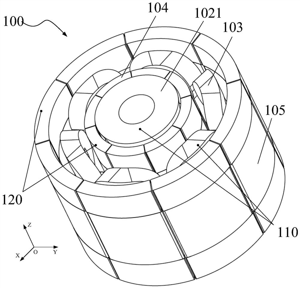
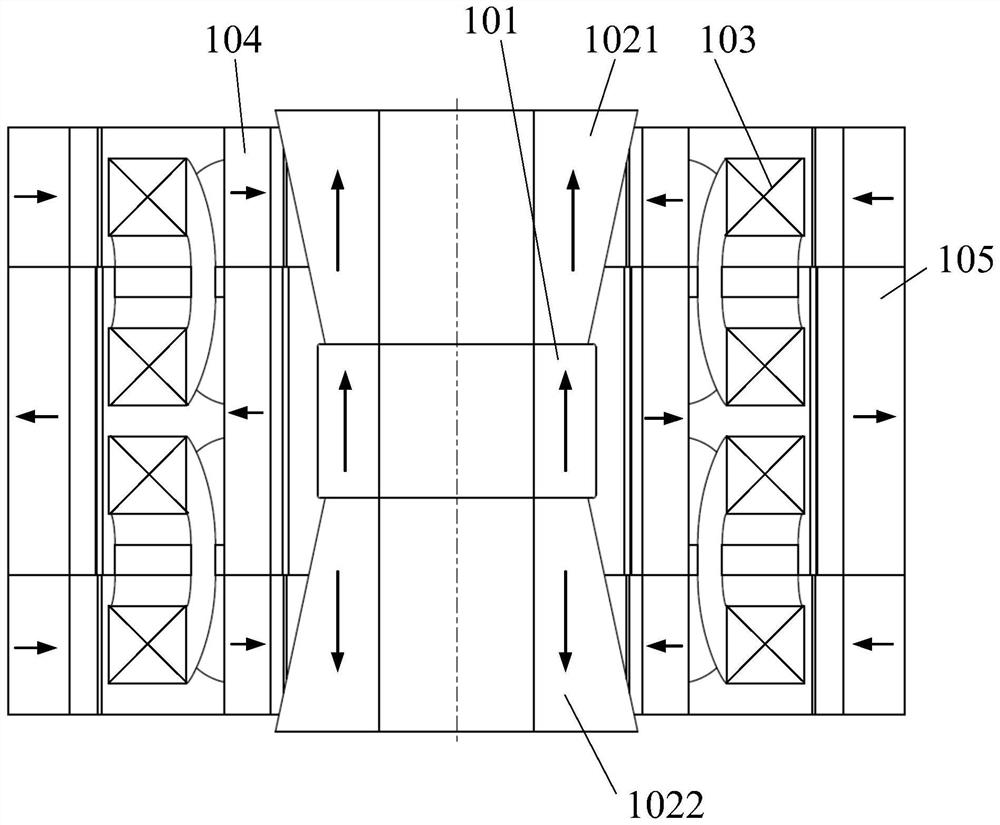
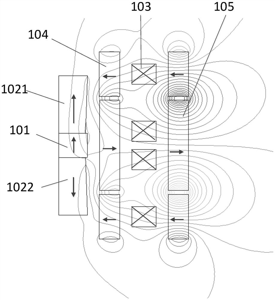
The invention discloses a magnetic levitation device which comprises an inner base magnet, first end magnetic steel, second end magnetic steel, an inner magnetic ring magnetic steel array and a coil array, and the inner base magnet extends in the axial direction; the first end magnetic steel and the second end magnetic steel are located at the two axial ends of the inner base magnet respectively and extend in the axial direction, and the outer diameter of the first end magnetic steel and the outer diameter of the second end magnetic steel are gradually increased in the direction away from the two axial ends of the inner base magnet respectively. The inner magnetic ring magnetic steel array comprises at least one piece of inner magnetic steel which is sequentially arranged along the axis, the inner magnetic steel is cylindrical, each piece of inner magnetic steel and the inner base magnet are coaxially arranged, and the inner magnetic ring magnetic steel array is located outside the inner base magnet and is spaced from the inner base magnet in the radial direction; the coil array comprises a plurality of coils which are arranged in the circumferential direction and spaced in the circumferential direction, and the coil array is located outside the inner magnetic ring magnetic steel array and spaced from the inner magnetic ring magnetic steel array in the radial direction; wherein the inner base magnet, the first end magnetic steel, the second end magnetic steel and the coil array are relatively fixed.

Description

technical field [0001] The invention relates to the field of integrated circuit equipment manufacturing, and more particularly relates to a magnetic levitation device and a micro-motion stage including the device. Background technique [0002] In the field of semiconductor manufacturing or testing, the workpiece table is required to have the precise positioning function of the silicon wafer, and the core actuator in the workpiece table is the micro-motion table, which can realize the precise positioning of the Z, Rx and Ry vertical three-axis of the silicon wafer. Usually, the vertical three-axis micro-motion stage adopts a three-point actuator layout. In order to ensure the vertical performance, a flexible mechanism (such as an elastic sheet, etc.) can be used as the motion decoupling and guidance of the micro-motion stage. Within the range, the elastic stiffness of the flexible mechanism is a constant value, and the reaction force acting on the vertical actuator changes li...

Claims


Application Information

Patent Timeline
Patent Type & Authority Applications(China)
IPC IPC(8): H01L21/677H01L21/68H01L21/687
CPCH01L21/67709H01L21/68785H01L21/68
Inventor 彭仁强胡兵江旭初袁嘉欣
Owner YINGUAN SEMICON TECH CO LTD
Learn More