

Plank slotting machine
A slotting machine and wood board technology, applied in the field of wood board processing, can solve problems such as low work efficiency, achieve the effects of reducing labor intensity, improving work efficiency, and reducing potential safety hazards
Pending Publication Date: 2018-10-26
重庆哲骁装饰工程有限公司
View PDF0 Cites 17 Cited by
- Summary
- Abstract
- Description
- Claims
- Application Information
AI Technical Summary
Problems solved by technology
[0003] The purpose of the present invention is to provide a wood slotting machine to solve the problem of low work efficiency due to the need to manually turn over the wood when slotting
Method used
View moreImage
Smart ImageViewing Examples

Examples
Embodiment Construction
[0016] The present invention will be described in further detail below by means of specific embodiments:
Login to View More PUM
 Abstract
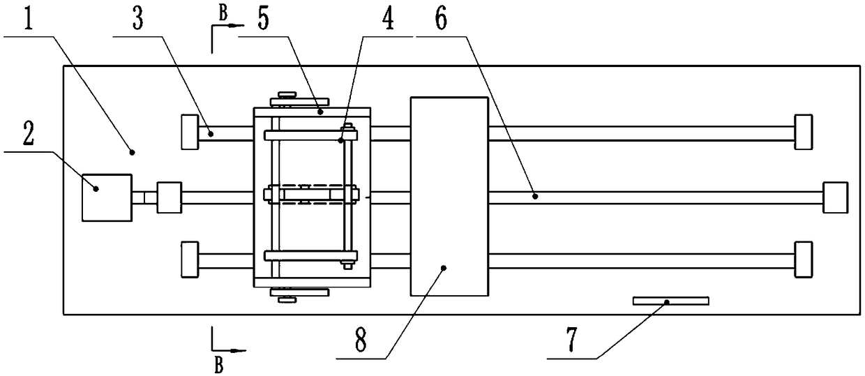
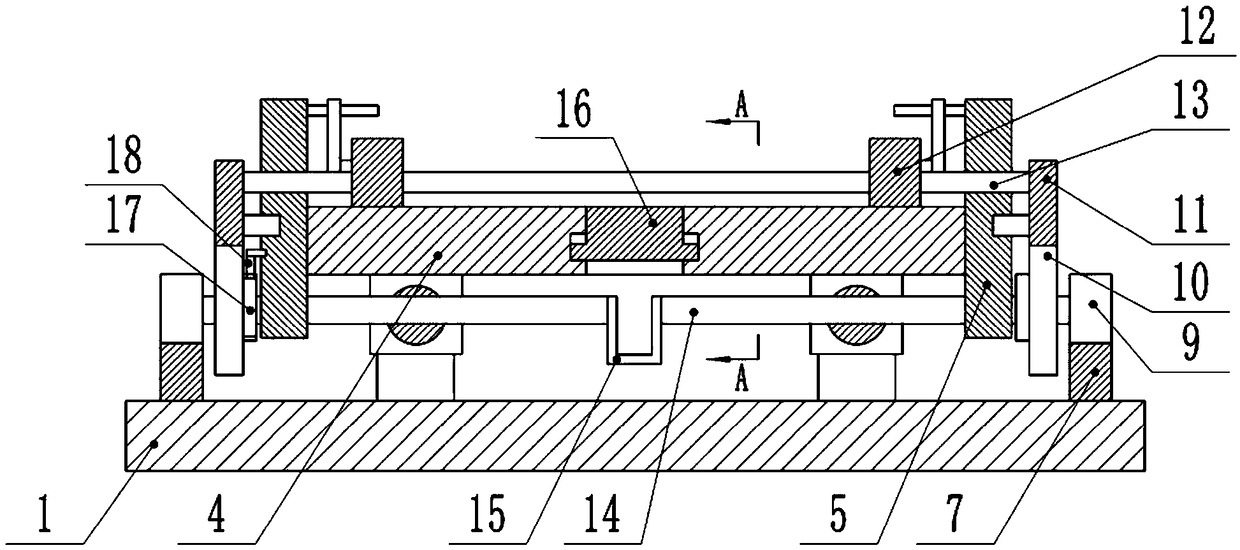
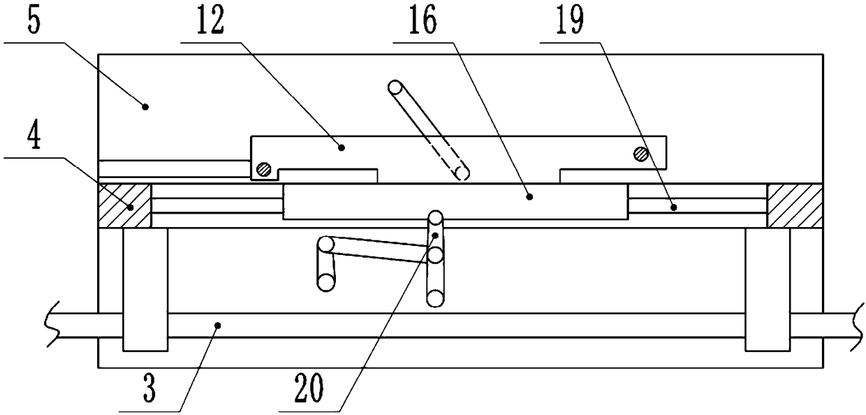
The invention belongs to the technical field of plank processing and particularly discloses a plank slotting machine. The plank slotting machine comprises a workbench, the workbench is slidably provided with a sliding plate and a power mechanism for driving the sliding plate. The sliding plate is provided with two clamping plates. A slotting mechanism is arranged above the sliding plate. First racks are arranged at the positions, on the two sides of the sliding plate, of the workbench. The two sides of the sliding plate are provided with side plates, the side plates are provided with first gears and second gears, and the side plates are slidably connected with second racks meshed with the second gears. The ends of the second racks are hinged to the clamping plates. A movable rod is hingedbetween the middle of the clamping plates and the upper portions of the side plates. The middle of the sliding plate is slidably connected with a polishing block, and the second gears are connected with transmission mechanisms for driving the polishing block to perform reciprocating movement. In the work process of the plank slotting machine, automatic turning-over of a plank can be realized, thetwo sides of the plank are subjected to slotting, and slotting efficiency is high; and meanwhile, slots formed in the plank are subjected to polishing treatment through the polishing block, and the manual labor intensity is lowered.
Description
technical field [0001] The invention belongs to the technical field of wood board processing, in particular to a wood board slotting machine. Background technique [0002] There are many wood processing operations, including cutting, nailing and other operations. For the slotting of wood boards, the current processing method is manual operation, the cutting wheel is fixed, and then the operator pushes the wood board to the cutting wheel, so that There are certain safety hazards in manual operation, and the labor intensity of the staff is high, and many wooden boards are usually slotted on both sides of the board for assembly needs, so the operation is usually After slotting one side of the board, Manually turn over the plank, and then slot the other side of the plank. The above-mentioned operation process is complicated, and the continuity of the slotting is not high, resulting in low work efficiency. Contents of the invention [0003] The object of the present invention ...
Claims
Login to View More Application Information
Patent Timeline
 Patent Type & AuthorityApplications(China)
IPC IPC(8): B27F5/02
CPCB27F5/02
Inventor邓月全
Owner重庆哲骁装饰工程有限公司