
Novel steel pipe pile foundation for preventing pile circumferential soil from being liquefied under action of waves

A technology for steel pipe piles and soil surrounding the piles, applied in soil protection, infrastructure engineering, sheet pile walls, etc., can solve problems such as displacement response control problems, and achieve the effects of saving material consumption, small environmental impact, and quick results.

Inactive Publication Date: 2018-10-26
HOHAI UNIV
View PDF5 Cites 4 Cited by
  • Summary
  • Abstract
  • Description
  • Claims
  • Application Information

AI Technical Summary

Problems solved by technology

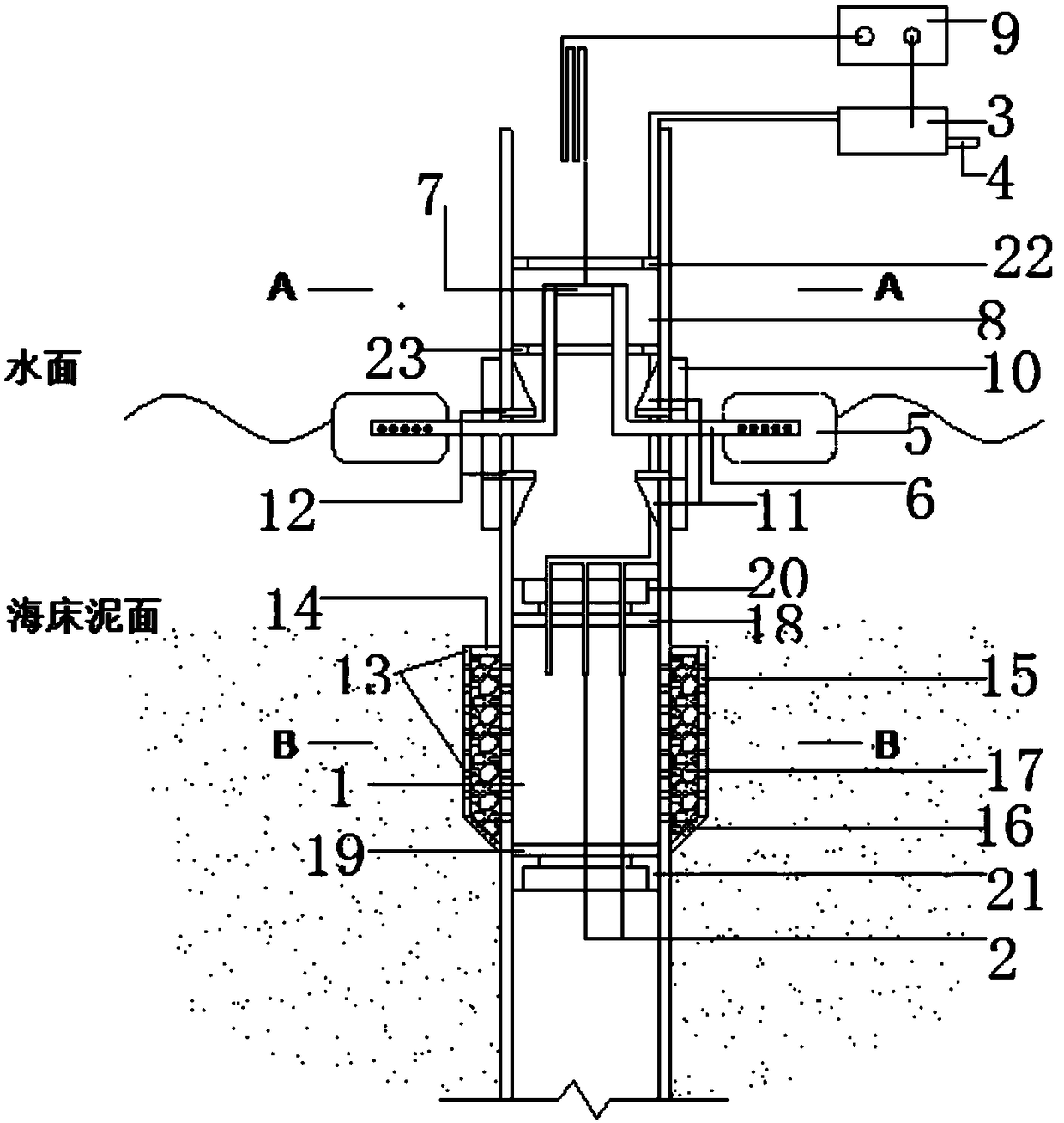
[0005] Purpose of the invention: The technical problem solved by the present invention is the displacement response control problem of the pile foundation in the sandy seabed under the action of waves in marine engineering. A new type of steel pipe pile foundation is proposed, which can convert wave energy into soil around the pile. The electric energy enhanced by the penetration of the body, thereby reducing the accumulation of pore water pressure in the soil around the pile, inhibiting the liquefaction of the soil under the action of waves, and achieving the purpose of controlling the adverse response of the pile foundation under the action of waves

Method used


Image

  • Novel steel pipe pile foundation for preventing pile circumferential soil from being liquefied under action of waves
  • Novel steel pipe pile foundation for preventing pile circumferential soil from being liquefied under action of waves
  • Novel steel pipe pile foundation for preventing pile circumferential soil from being liquefied under action of waves

Examples


Embodiment Construction

[0026] The application will be described in detail below in conjunction with the accompanying drawings.

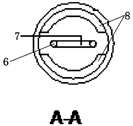
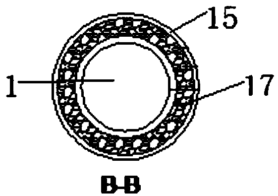
[0027] Such as figure 1 , figure 2 and image 3 A new type of steel pipe pile foundation is shown to prevent the liquefaction of the soil around the pile under the action of waves. There is a vacuum chamber 1 in the steel pipe pile under the seabed mud surface, and the vacuum chamber 2 is fixed by the steel pipe pile wall and the corresponding The upper top plate 18 and the lower top plate 19 in the pile section are composed, wherein, the upper top plate 18 and the lower top plate 19 are disc-shaped plates and are respectively welded to the inner wall of the pile through the annular upper support ring 20 and the lower support ring 21; the above-mentioned vacuum The chamber 1 is connected to the vacuum pump 3 through the suction pipe 2, and the vacuum pump 3 is provided with a drainage port 4, and meanwhile, drainage holes are distributed on the pile wall corresponding t...


PUM


Abstract

The invention discloses a novel steel pipe pile foundation for preventing pile circumferential soil from being liquefied under an action of waves. The novel steel pipe pile foundation is characterizedin that a vacuum cavity is formed in a steel pipe pile below a seabed mud surface, the vacuum cavity is connected to a vacuum pump through a suction pipe, the vacuum pump is provided with a water outlet, drainage holes are distributed in the wall of the steel pipe pile corresponding to the vacuum cavity, water is permeated to the pile circumferential soil and enters the vacuum cavity through thedrainage holes, and then under the action of the vacuum pump, the pile circumferential soil is discharged to the vacuum pump through the suction pipe and then is discharged from the water outlet; andpreference is given, the device can further comprise a wave energy conversion section, a permeation layer expansion section and the like. According to the novel steel pipe pile foundation, the pore water pressure caused by the waves is reduced on the premise that the property of the pile circumferential soil is not changed, so that the liquefaction is prevented and the environment influence is small; the vacuum suction force is manufactured by utilizing the wave energy, and extra energy consumption is not needed; and the effect area of the pile soil is expanded by the permeation layer expansion section, so that the soil resistance is fully obtained so as to reduce the displacement response of the pile foundation under the action of the waves.

Description

technical field [0001] The invention belongs to the field of foundation engineering of marine structures, and relates to the control of disaster response of steel pipe pile foundations under the action of waves and the effective utilization of wave energy. technical background [0002] With the further increase in the demand for energy and the rapid development of new energy technologies, more and more marine engineering structures are being built and used. As one of the most commonly used foundation forms for marine engineering structures, steel pipe pile foundations are subject to more complex loads than those located in land environments, in which wave action is the main load source. On the one hand, the wave propagation directly acts on the pile foundation, and then produces the horizontal cyclic load that causes the horizontal displacement response of the pile foundation; on the other hand, when the pile foundation is located on the sandy seabed, the continuous and stro...

Claims


Application Information

Patent Timeline
Patent Type & Authority Applications(China)
IPC IPC(8): E02D3/10E02D5/38E02D5/52E02D27/52F03B13/18
CPCE02D3/10E02D5/38E02D5/526E02D27/52E02D2250/0053F03B13/1815Y02E10/30
Inventor 黄挺张继生白顺亚郭中元
Owner HOHAI UNIV
Learn More