

External air monitoring device
A technology for monitoring equipment and outside air, applied in the field of outside air monitoring equipment, can solve problems such as inability to collect and inspect, poor particle monitoring effect, etc., and achieve the effects of reducing air pollution concentration, reducing emissions, and improving air quality
- Summary
- Abstract
- Description
- Claims
- Application Information
AI Technical Summary
Problems solved by technology
Method used
Image

Examples
Embodiment
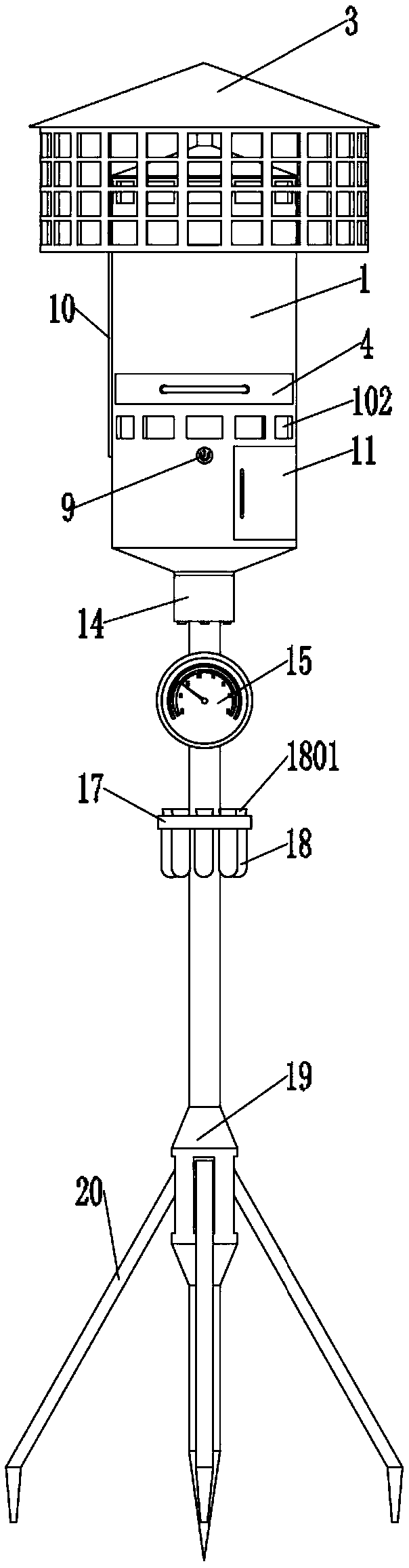
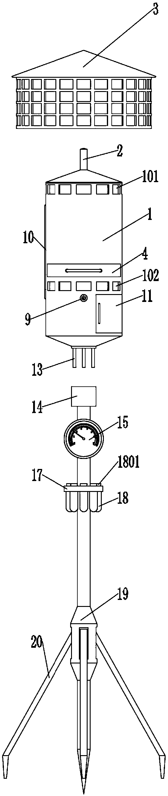
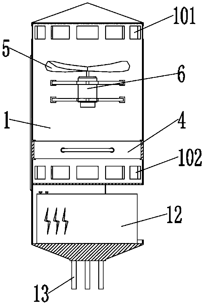
[0036] as attached figure 1 to attach Figure 9 Shown:
[0037]The present invention provides an external air monitoring device, comprising a particle collection body 1, an air inlet 101, an air outlet 102, a top cover support column 2, a waterproof top cover 3, a particle collection block 4, a handle 401, a blade 5, and an electric motor 6 , motor support frame 7, particle blocking net 8, power switch 9, power cord 10, sealing plate 11, battery 12, connecting column 13, connecting block 14, connecting hole 1401, hygrometer 15, supporting column 16, assembly hole 1601, Test tube storage plate 17, particle storage test tube 18, test tube plug 1801, fixed block 19 and fixed column 20, the particle collection body 1 is a cylindrical hollow structure, and the top of the outer end surface of the particle collection body 1 is provided with twelve air inlets 101, and the air inlet 101 communicates with the inside of the particle collection body 1, ten air outlets 102 are opened at ...
PUM
 Abstract
Description
Claims
Application Information