
Multi-station permanent magnetic motor assembling device

A permanent magnet motor and assembly equipment technology, which is applied in electromechanical devices, manufacturing motor generators, electrical components, etc., can solve the problems of easily damaged end caps and rotors, increased product scrap rate, low work efficiency, etc., and reduces the number of workers. The effect of reducing the amount of labor, reducing the motor scrap rate and improving work efficiency

Active Publication Date: 2018-10-26
芜湖翡叶动力科技有限公司
View PDF4 Cites 3 Cited by
  • Summary
  • Abstract
  • Description
  • Claims
  • Application Information

AI Technical Summary

Problems solved by technology

[0003] As we all know, when the permanent magnet motor is assembled, because the rotor of the motor is magnetic, it will attract each other with the stator, which makes it deviate from the centerline of the end cover installation hole on the stator, easily damage the end cover and the rotor itself, and increase the product rejection rate. At the same time, the traditional motor assembly can only achieve one-to-one installation, which requires a lot of labor and low work efficiency

Method used


Image

  • Multi-station permanent magnetic motor assembling device
  • Multi-station permanent magnetic motor assembling device
  • Multi-station permanent magnetic motor assembling device

Examples


Embodiment Construction

[0021] In order to make the technical means, creative features, goals and effects achieved by the present invention easy to understand, the present invention will be further elaborated below.

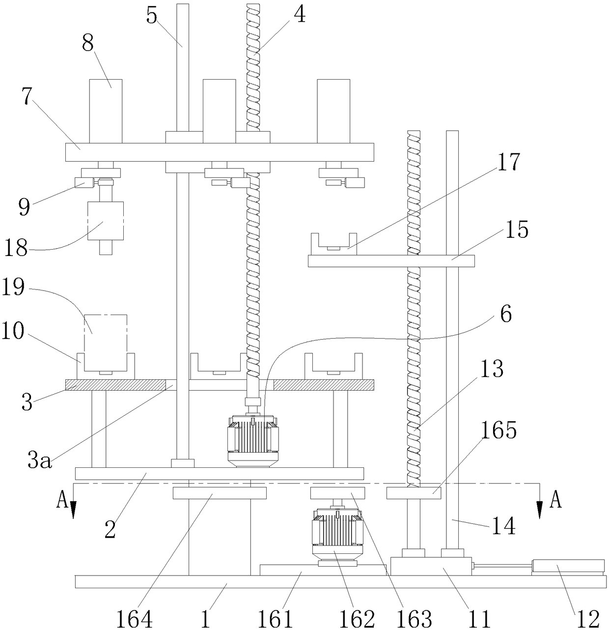
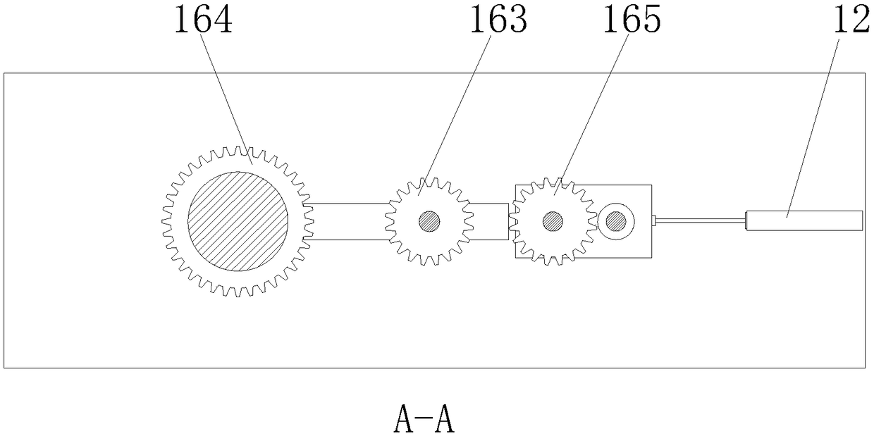
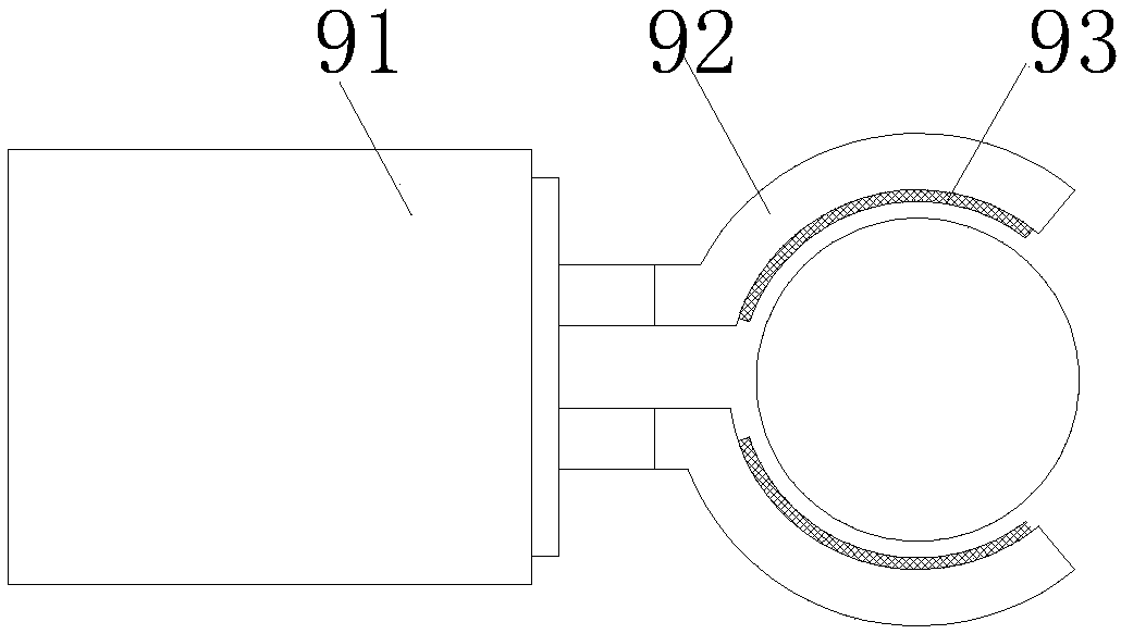
[0022] Such as Figure 1 to Figure 4 As shown, a multi-station permanent magnet motor assembly equipment includes a bottom plate 1, a rotary table 2 is rotatably connected to the bottom plate 1, a stator mounting table 3 is provided on the rotary table 2, and the stator mounting table 3 passes through the The set screw 4 and the guide rod 5 are connected with the motor 6, the screw 4 and the guide rod 5 are jointly connected with a rotor mounting table 7, and the upper ring of the rotor mounting table 7 is provided with several Hydraulic cylinders 8, the output end of any hydraulic cylinder 8 passes through the rotor installation platform 7 and is connected with a jaw mechanism 9 for clamping the rotor 18, and the lower side of any hydraulic cylinder 8 corresponds to a It is used to pl...


PUM


Abstract

The invention relates to a multi-station permanent magnetic motor assembling device. The device comprises a base plate and a rotary bench. A stator installation bench, a lead screw penetrating throughthe stator installation bench and a guidance rod are arranged on the rotary bench. The lead screw is connected with a motor. A rotor installation bench is connected to the lead screw and the guidancerod. Multiple hydraulic cylinders are arranged on the rotor installation bench in a cycle manner. A clamping jaw mechanism is connected to each hydraulic cylinder. A limiting seat is correspondinglyarranged on the lower side of each hydraulic cylinder. A moving plate is slidably connected to the right side of the base plate. An air cylinder connected with the moving plate is fixed on the base plate. Screws and sliding columns are arranged on the moving plate. Rotor loading plates are connected to the screws and the sliding columns. Rotor installation seats are fixed to the left ends of the rotor loading plates. A power mechanism for driving the rotation bench and the screws to rotate is arranged on the base plate. According to the invention, it can be ensured that the assembling positions of the rotor and the stator of the permanent magnetic motor are precise; the rotor is prevented from deflecting; motor rejection rate is reduced; multiple stators and rotors can be assembled; rotorscan be loaded; labor intensity is reduced; and working efficiency is improved.

Description

technical field [0001] The invention relates to the technical field of motor assembly machinery, in particular to a multi-station permanent magnet motor assembly equipment. Background technique [0002] Permanent magnet motor is also called rare earth permanent magnet motor, which has excellent performance. Its advantage is that it can establish a strong permanent magnetic field without external energy after magnetization. Compared with traditional motors, it is not only efficient, but also simple in structure and reliable in operation. , Small size and light weight. It has been widely used in various fields of aviation, aerospace, national defense, equipment manufacturing, industrial and agricultural production and daily life. Permanent magnet motors also include permanent magnet synchronous motors, permanent magnet generators, DC motors, brushless DC motors, AC permanent magnet Servo motors, permanent magnet linear motors, special permanent magnet motors and related contr...

Claims


Application Information

Patent Timeline
IPC IPC(8): H02K15/00H02K15/16
CPCH02K15/00H02K15/16
Inventor 彭兴
Owner 芜湖翡叶动力科技有限公司
Learn More