
Configurable microwave photon channelization receiving device

A receiving device, microwave photon technology, applied in the direction of electromagnetic receivers, etc., can solve the problems of difficult to reduce channel bandwidth, high price, and inability to monitor the detection range at the same time, achieve convenient digital processing and storage, and realize channelized reception and digitization Effect

Active Publication Date: 2018-10-26
SHANGHAI JIAO TONG UNIV
View PDF9 Cites 5 Cited by
  • Summary
  • Abstract
  • Description
  • Claims
  • Application Information

AI Technical Summary

Problems solved by technology

Some photon channelization receiving schemes require multiple lasers (Strutz S J, Williams K J.An 8-18-GHz all-optical microwave downconverter with channelization[J].IEEE Transactions on Microwave Theory and Techniques,2001,49(10):1992 -1995.) The structure is complex and the price is high. Some photon channelization receiving schemes are based on time-domain sweeping, which cannot monitor the entire detection range at the same time (Chen H, Chen M, Li R, et al. Multiple-frequency measurement based on serial photonic channelization using opticalwavelength scanning[J].Optics Letters,2013,38(22):4781-4.)
In addition, the optical filters (such as: Fabry-Perot filter) used in most schemes have a large bandwidth, and it is difficult to improve the resolution by reducing the channel bandwidth
Simultaneously simulated photonic channelization receiving device is difficult to distinguish the specific frequency of the microwave signal received in each sub-band

Method used


Image

  • Configurable microwave photon channelization receiving device
  • Configurable microwave photon channelization receiving device
  • Configurable microwave photon channelization receiving device

Examples


Embodiment Construction

[0023] The present invention will be further described below in conjunction with drawings and embodiments. The examples are carried out on the premise of the technical solutions of the present invention, and detailed implementation methods and processes are given, but the protection scope of the present invention is not limited to the following examples.

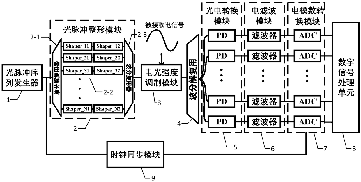
[0024] The system block diagram of the embodiment of the present invention is as figure 1 As shown, it can be seen from the figure that the configurable microwave photon channelization receiving device of the present invention includes an optical pulse sequence generator 1, and along the laser output direction of the optical pulse sequence generator 1 is an optical pulse shaping module 2, an electro-optic Intensity modulation module 3, second wave decomposition multiplexing module 4, photoelectric conversion module 5, electrical filter module 6, electrical analog-to-digital conversion module 7, digital signal processing unit...


PUM


Abstract

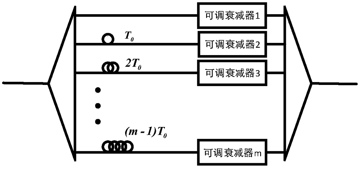
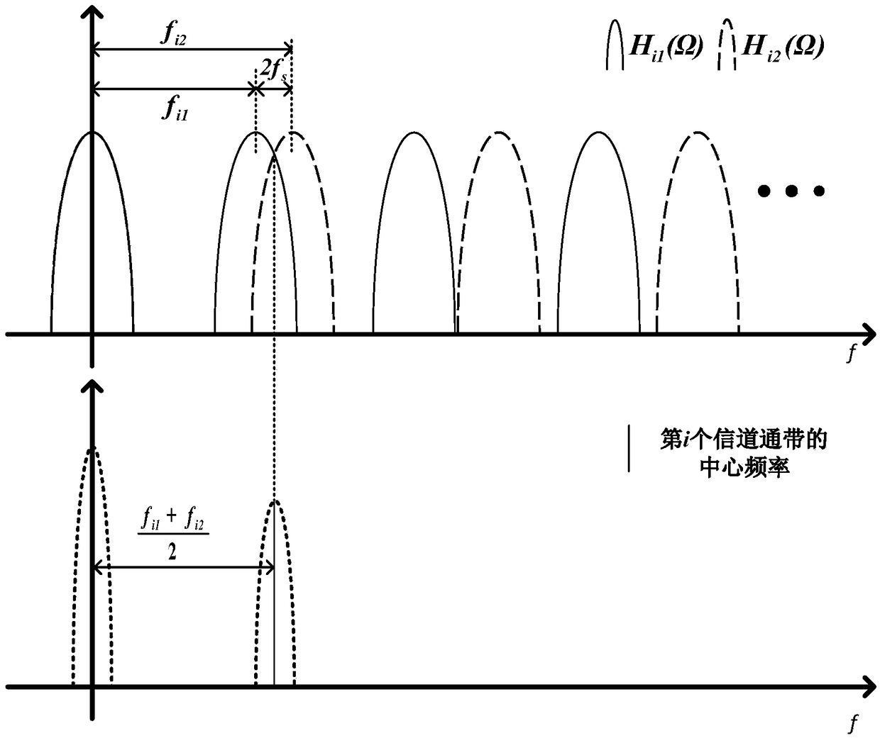
The invention discloses a configurable microwave photon channelization receiving device. The device includes an optical pulse sequence generator, an optical pulse shaping module, an electro-optic intensity modulation module, a second wave division multiplexing module, a photoelectric conversion module, an electrical filter module, an electrical analog to digital conversion module, a digital signalprocessing unit and a clock synchronization module. The device can simultaneously realize the multichannel receiving and analog-to-digital conversion of broadband signals, that conventional optical channelization receiving devices subject to passband bandwidth limitation when adopting devices like optical filters can be avoided; convenience can be provided for further digital processing and storage by converting receiving signals into digital signals; and the center frequency and bandwidth of each channel can perform configuration by adjusting the tap intervals of a multi tap optical pulse shaper and the bandwidth of an electric filter.

Description

technical field [0001] The invention relates to microwave signal channelization reception, in particular to a configurable microwave photon channelization reception device. Background technique [0002] In modern warfare, modern electronic warfare (EW) techniques against information systems have been widely used. As an important part of the electronic reconnaissance and support system, the electronic reconnaissance receiver is also facing more and more serious tests. In a complex signal environment, the receiver is required to have large instantaneous reconnaissance bandwidth, high sensitivity, high resolution and large dynamic range, and be able to conduct undistorted reconnaissance reception and real-time processing of simultaneously arriving multi-frequency points and multi-form signals ( Schleher DC. Electronic warfare in the information age [M]. Artech House, Inc., 1999.). [0003] To meet the requirement of detecting multi-frequency signals at the same time, a channe...

Claims


Application Information

Patent Timeline
IPC IPC(8): H04B10/60
CPCH04B10/60
Inventor 吴龟灵王思同孙一唯陈建平
Owner SHANGHAI JIAO TONG UNIV
Learn More