Automobile exhaust pipe with exhaust treatment function and convenient to clean
A technology for exhaust gas treatment and automobile exhaust, which is applied in exhaust devices, air quality improvement, noise reduction devices, etc., and can solve problems such as corneal damage, dermatitis, conjunctivitis, and hazards
- Summary
- Abstract
- Description
- Claims
- Application Information
AI Technical Summary
Problems solved by technology
Method used
Image
Examples
Embodiment 1
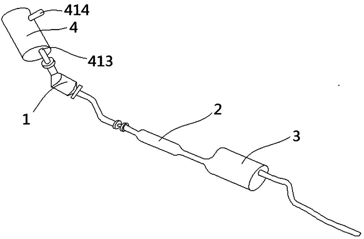
[0030] An automobile exhaust pipe with tail gas treatment function and easy to clean, such as Figure 1-3 As shown, it includes a catalytic converter 1, a first muffler 2 and a second muffler 3 that are connected in sequence through pipelines, the air intake pipe 414 of the catalytic converter 1 is connected with a particle processor 4, and the air outlet 413 of the particle processor 4 A pipe is arranged at the end of the pipe, and a flange is fixed at the end of the pipe, and the particle processor 4 is connected with the catalytic converter 1 through the flange.
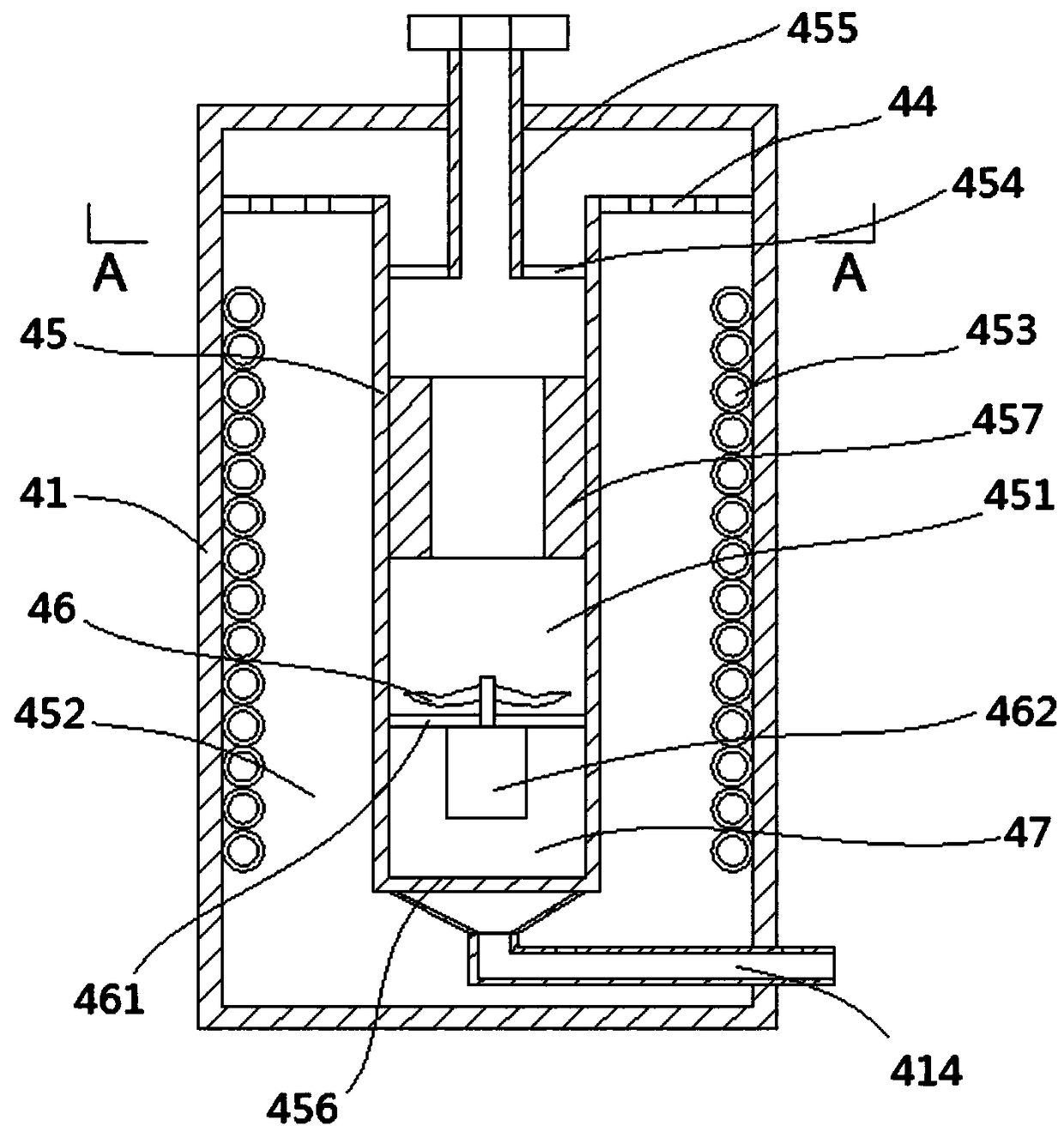
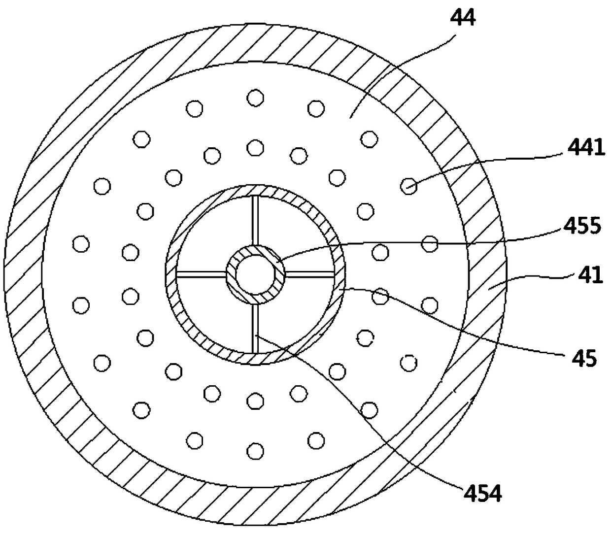
[0031] The particle processor 4 includes a cylindrical body 41 with a closed inner cavity; the upper end of the cylindrical body 41 is provided with an annular partition 44, and the outer wall of the annular partition 44 is fixed on the inner wall of the cylindrical body 41; the annular partition The middle part of the plate 44 is fixed with an insulating tube 45 with an upper end opening, and the outer wall of th...
Embodiment 2
[0039] Such as Figure 4-Figure 6 As shown, it is the same as in Embodiment 1, the difference is that the cylindrical body 41 in this embodiment includes an upper end plate 415, an annular side wall 416 and a lower end cover 417, the upper end plate 415 and the annular side wall 416 are integrally formed, and the lower end cover 417 is flexibly connected On the lower end of the annular side wall 416 .
[0040] Wherein, the inner wall of the lower end cover 417 is fixed with a fixed ring plate 431 whose axis is the same as that of the lower end cover 417. The upper surface of the fixed ring plate 431 is provided with a cylindrical ring 432. On the inner and outer walls of the cylindrical ring 432 Both are provided with elastic limiters 433 whose longitudinal section is triangular. The side wall of the lower end cover 417 is also provided with a movable ring plate 434 that can move up and down and is parallel to the fixed ring plate 431. The movable ring plate 434 The plate sur...
Embodiment 3
[0044] Such as Figure 7-Figure 9 As shown, it is the same as in Embodiment 1, except that the cylindrical body 41 in this embodiment includes an upper cylinder 411 with an open lower end and a lower cylinder 412 with an open upper end, the upper part of the lower cylinder 412 is inserted into the upper cylinder 411 and the two The bottom of the lower cylinder 412 is fixed with a fabric net 42 and a fabric net fixing mechanism 43, and the fabric net fixing mechanism 43 includes a fixed ring plate 431 fixed on the inner wall of the lower cylinder 412 with the same axis as the lower end cover. The upper surface of the ring plate 431 is provided with a cylindrical ring 432, and the inner and outer walls of the cylindrical ring 432 are provided with elastic stoppers 433 whose longitudinal section is triangular in shape, and the side wall of the lower end cover is also provided with an upper and lower Moving and the movable annular plate 434 that is arranged parallel to the fixed a...
PUM
 Abstract
Description
Claims
Application Information
 - R&D
- Intellectual Property
- Life Sciences
- Materials
- Tech Scout
- Unparalleled Data Quality
- Higher Quality Content
- 60% Fewer Hallucinations
Browse by: Latest US Patents, China's latest patents, Technical Efficacy Thesaurus, Application Domain, Technology Topic, Popular Technical Reports.
© 2025 PatSnap. All rights reserved.Legal|Privacy policy|Modern Slavery Act Transparency Statement|Sitemap|About US| Contact US: help@patsnap.com


