Negative pressure detection circuit applicable to dead-time control

A dead time control, negative pressure detection technology, applied in the direction of measuring electricity, measuring electrical variables, measuring devices, etc., can solve the problem of not being able to guarantee reliability and detection performance at the same time, and achieve the effect of avoiding false triggering

Active Publication Date: 2018-10-30
UNIV OF ELECTRONICS SCI & TECH OF CHINA
View PDF12 Cites 7 Cited by
  • Summary
  • Abstract
  • Description
  • Claims
  • Application Information

AI Technical Summary

Problems solved by technology

[0005] Aiming at the problem that the traditional negative pressure detection circuit adopting the source-side input comparator structure cannot guarantee reliability and detection performance at the same time, the present invention proposes a negative pressure detection circuit suitable for dead time, which can fit the drive switching stage The PVT change of the on-resistance of the power tube effectively improves the detection performance while ensuring the reliability of the negative voltage detection circuit

Method used


Image

  • Negative pressure detection circuit applicable to dead-time control
  • Negative pressure detection circuit applicable to dead-time control
  • Negative pressure detection circuit applicable to dead-time control

Examples


Embodiment Construction

[0025] The present invention will be further described in detail below in conjunction with the accompanying drawings and specific embodiments.

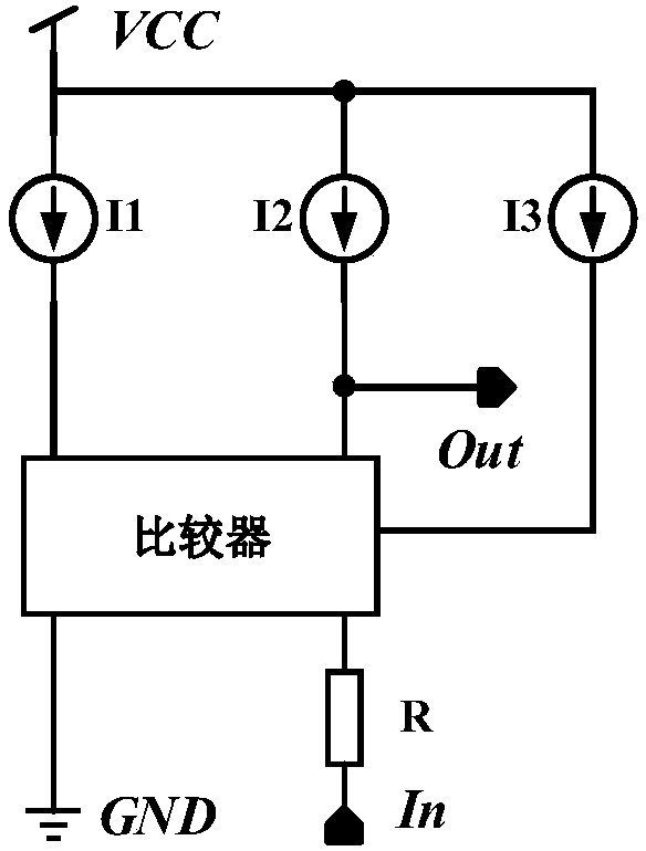
[0026] The negative voltage detection circuit proposed by the present invention is suitable for dead-time control of BUCK step-down switching power supply. By comparing the voltage at the switch node SW of the BUCK step-down switching power supply with the set value, the BUCK step-down switch The voltage at the switching node SW of the power supply is subjected to negative voltage detection, such as figure 1 Shown is the principle equivalent diagram of the present invention, by fitting the PVT characteristics of the on-resistance of the power tube of the BUCK step-down switching power supply through the resistor R, and comparing the output voltage of the resistor R with the ground voltage GND to obtain negative voltage detection output signal of the circuit.

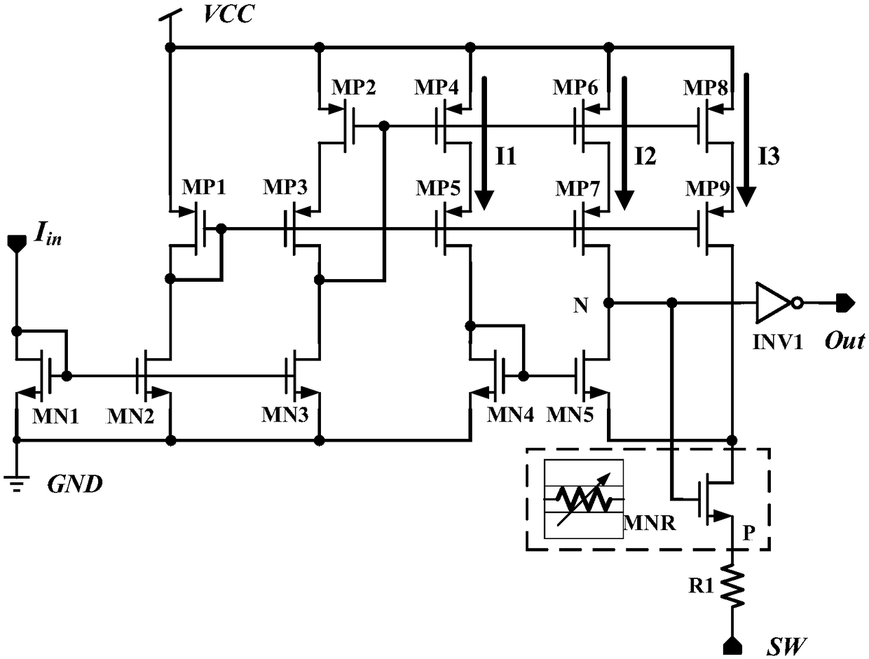
[0027] like figure 2 As shown, in the present invention, the resistor ad...


PUM


Abstract

The invention discloses a negative pressure detection circuit applicable to dead-time control, belonging to the technical field of electronic circuits. The negative pressure detection circuit comprises a comparator, a resistor and a current generation module, wherein the current generation module is used for generating first bias current, second bias current and third bias current; the resistor comprises a first resistor and a sixth NMOS (N-channel Metal Oxide Semiconductor) transistor; one end of the first resistor serves as the input end of the negative pressure detection circuit, and the other end of the first resistor is connected with a source of the sixth NMOS transistor; the grid of the sixth NMOS transistor is connected with the second bias current; the drain is connected with thethird bias current and the second input end of the comparator; the comparator comprises a fourth NMOS transistor, a fifth NMOS transistor and a phase inverter; the grid and drain of the fourth NMOS transistor are in short circuit, and the fifth NMOS transistor is connected with the grid of the fifth NMOS transistor and the first bias current, and the source serves as a first input end of the comparator to be grounded; the source of the fifth NMOS transistor serves as a second input end of the comparator; the drain is connected with the input end of the phase inverter and the grid of the sixthNMOS transistor; and the output end of the phase inverter serves as the output end of the negative pressure detection circuit. According to the negative pressure detection circuit disclosed by the invention, the reliability and the detection performance can be ensured simultaneously.

Description

technical field [0001] The invention belongs to the technical field of electronic circuits and relates to a negative pressure detection circuit suitable for dead zone time control. Background technique [0002] With the continuous development of semiconductor technology, the improvement of chip efficiency has become a crucial link in chip design. Among them, in the step-down switching power supply (BUCK) chip design using synchronous rectification technology, whether the dead time setting is reasonable or not directly affects the level of its system conversion efficiency. [0003] In order to optimize the dead time and effectively improve the chip conversion efficiency, various dead time adjustment technologies have been proposed at home and abroad. These technologies can be mainly divided into two categories: adaptive dead time adjustment technology and pre-control dead time adjustment technology. However, whether it is the adaptive dead time adjustment technology or the ...

Claims


Application Information

Patent Timeline
Patent Type & Authority Applications(China)
IPC IPC(8): G01R31/26
CPCG01R31/2607
Inventor 周泽坤袁东石跃李响石旺李登维张波
Owner UNIV OF ELECTRONICS SCI & TECH OF CHINA
Why Eureka
Try Eureka