Improved creasing and cutting machine

A thread cutting machine and indentation technology, applied in the field of packaging paper cutting equipment, can solve problems such as hand pinching

Active Publication Date: 2018-11-02
深圳市益华兴包装制品有限公司
View PDF8 Cites 2 Cited by
  • Summary
  • Abstract
  • Description
  • Claims
  • Application Information

AI Technical Summary

Problems solved by technology

[0004] During the cutting process of a piece of paper, the staff needs to put their hands into the flap twice; and each time the flap is rotated and pressed, the staff's hands are likely to be pinched

Method used


Image

  • Improved creasing and cutting machine
  • Improved creasing and cutting machine
  • Improved creasing and cutting machine

Examples


Embodiment 1

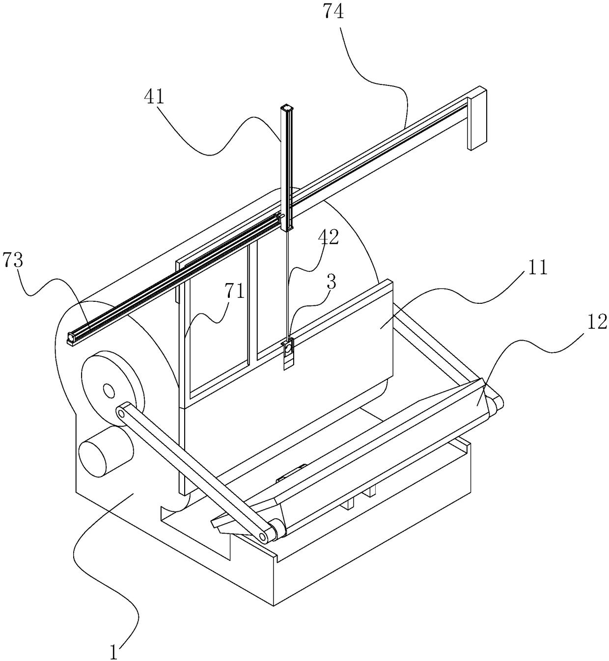
[0059] Embodiment 1, an improved creasing and thread cutting machine, as shown in Figure 1, includes a frame 1, a fixed plate 11 and a flap 12 are installed on the frame 1, and the flap 12 is rotationally connected with the main body of the frame 1, and the frame The crank mechanism on 1 drives the turning plate 12 to perform repeated pressing and opening actions towards the fixed plate 11; during this operation, the cutter mold will be placed in the fixed plate 11, and the staff will put the paper into the turning plate 12, A supporting member made of soft material is placed in the turning plate 12, and the paper is placed on the supporting member, and then the paper is cut by the cutter mold on the fixed plate 11 as the turning plate 12 rotates.

[0060] It can be seen that the upper end of the fixed plate 11 is fixed with a column 71 , and there are two columns 71 ; the upper ends of the two columns 71 are fixed with a horizontal slide rail 74 . The track line of slide rail...

Embodiment 2

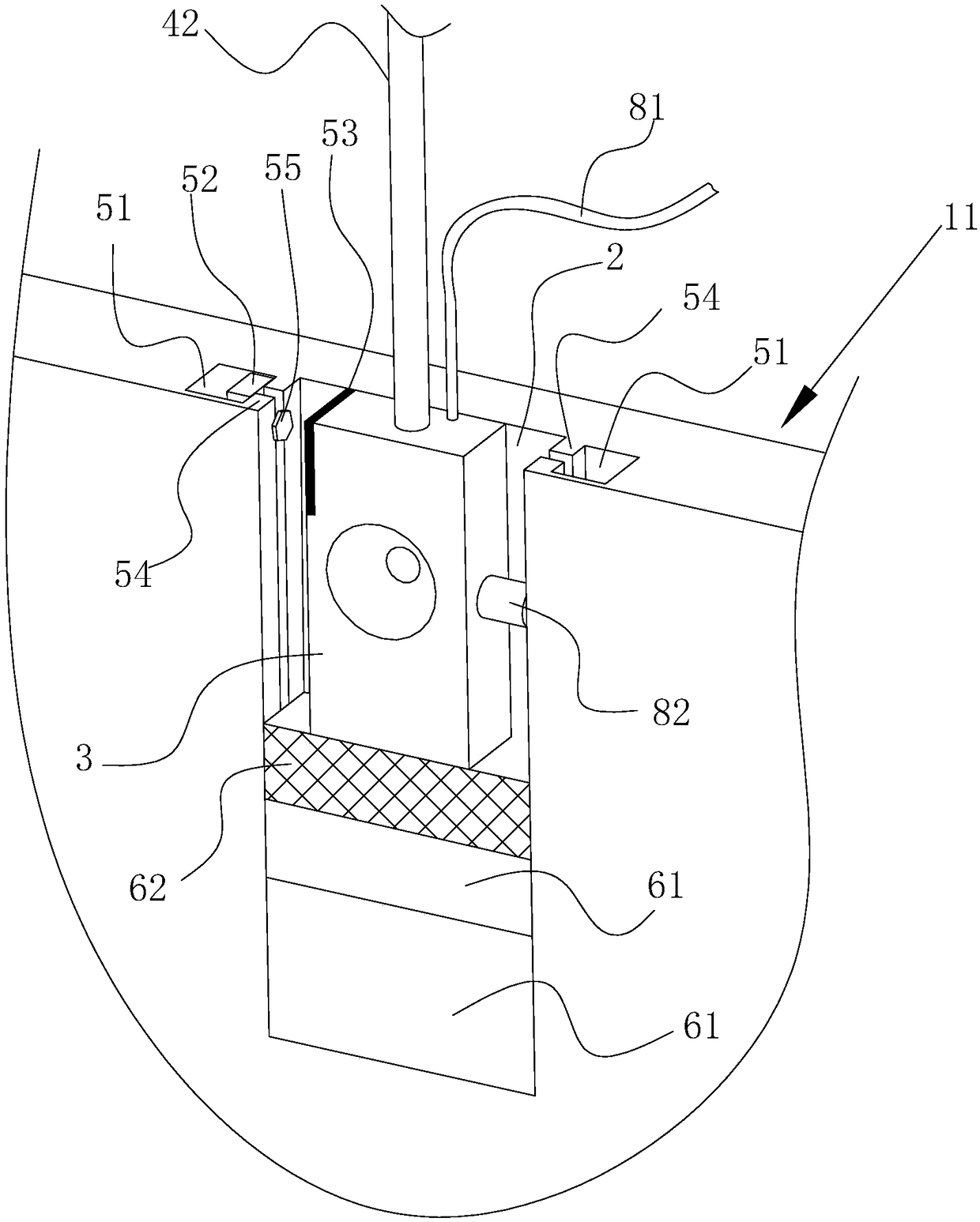
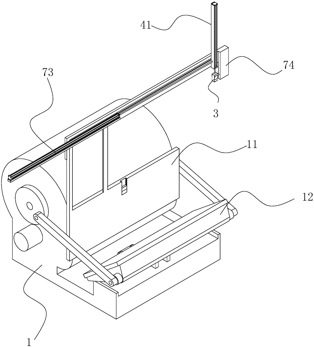
[0075] Embodiment 2, improved creasing and cutting machine, such as figure 2 and image 3 As shown, one side of the suction cup 3 is provided with a branch pipe 82, and the branch pipe 82 communicates with the air flow channel inside the suction cup 3. When the air pipe 81 urges the air flow passage in the suction cup 3 to inhale, due to the sealing of the branch pipe 82, the suction cup 3 has good airflow. of suction.

[0076] And be placed on frame 1 outer side on slide rail 74 and be fixed with block 74, block 74 is used for blocking vertical cylinder 41, prevents vertical cylinder 41 from slipping out slide rail 74; Of course, block 74 also has a function Just trigger branch pipe 82, make branch pipe 82 air leakage, then paper will lose the suction force of suction cup 3, and paper will fall freely.

[0077] As shown in FIG. 4 , the branch pipe 82 communicates with the inside of the suction cup 3 , and a spherical valve core 84 is installed in the branch pipe 82 . Unde...


PUM


Abstract

The invention discloses an improved creasing and cutting machine. According to the technical scheme, the improved creasing and cutting machine comprises a machine frame, a fixed plate fixed to the machine frame and a turning plate which is in press fit with the fixed plate rotatably. The improved creasing and cutting machine further comprises a sliding groove, a suction disc, a lifting assembly and a pushing assembly, wherein the sliding groove is vertically formed in the fixed plate, and a notch of the sliding groove faces the turning plate; the suction disc is arranged in the sliding groove,the suction disc penetrates through the notch of the sliding groove to realize the suction with paper; the lifting assembly is fixed to the suction disc and drives the suction disc to enter and exitthe sliding groove; and the pushing assembly drives the lifting assembly to reciprocate transversely so as to move the suction disc separated from the sliding groove out of the extrusion position between the fixed plate and the turning plate, so that the purposes of improving the production efficiency is achieved, the occurrence of safety accidents is reduced, and the improved creasing and cuttingmachine is more environment-friendly.

Description

technical field [0001] The present invention relates to a wrapping paper cutting device, more specifically, it relates to an improved creasing and cutting machine. Background technique [0002] When producing stickers with printed trademarks, it is necessary to cut the stickers, which requires the use of creasing and cutting machines. [0003] A Chinese patent document whose announcement number is CN204278086U is now retrieved, and its name is a flat creasing and cutting machine. When the machine is in use, the staff needs to put the paper into the flap, and then the flap is rotated and pressed; After the flap is opened again, the staff is taking out the cut paper. [0004] During the cutting process of a piece of paper, the staff needs to put their hands into the flap twice; and each time the flap is rotated and pressed together, there is a danger of the staff's hands being pinched. Contents of the invention [0005] The purpose of the present invention is to provide an...

Claims


Application Information

Patent Timeline
IPC IPC(8): B26D3/08B26D7/32
CPCB26D3/085B26D7/32
Inventor 易琳媛易宸源
Owner 深圳市益华兴包装制品有限公司
Why Eureka
Try Eureka