
Electrical equipment mounting rack with automatic lifting function

An electric power equipment and automatic lifting technology, which is applied in the direction of lifting equipment safety devices, hoisting devices, switching devices, etc., can solve problems such as easy collapse, cost of installation frames, inconvenience, etc., so that it is not easy to shake, not easy to collapse, and not easily damaged effects

Inactive Publication Date: 2018-11-02
WUHU SUNRISE NEW BUILDING MATERIALS TECH
View PDF2 Cites 4 Cited by
  • Summary
  • Abstract
  • Description
  • Claims
  • Application Information

AI Technical Summary

Problems solved by technology

[0003] However, most of the current mounting racks have simple structures and single functions, and have many limitations. Such devices are not equipped with guardrails, and the safety is not high. Workers are prone to accidents when installing equipment at high places, causing danger. At the same time, such devices Most of the structures are unstable and prone to collapse. In addition, this type of mounting frame cannot be automatically raised and lowered, which is very inconvenient for workers to use. Some mounting frames that can be automatically raised and lowered consume more power resources, and it is also inconvenient to use outdoors. Therefore be badly in need of a kind of power equipment mounting frame with automatic lifting function to satisfy people's demand

Method used


Image

  • Electrical equipment mounting rack with automatic lifting function
  • Electrical equipment mounting rack with automatic lifting function
  • Electrical equipment mounting rack with automatic lifting function

Examples


Embodiment Construction

[0017] The following will clearly and completely describe the technical solutions in the embodiments of the present invention with reference to the accompanying drawings in the embodiments of the present invention. Obviously, the described embodiments are only some, not all, embodiments of the present invention. Based on the embodiments of the present invention, all other embodiments obtained by persons of ordinary skill in the art without making creative efforts belong to the protection scope of the present invention.

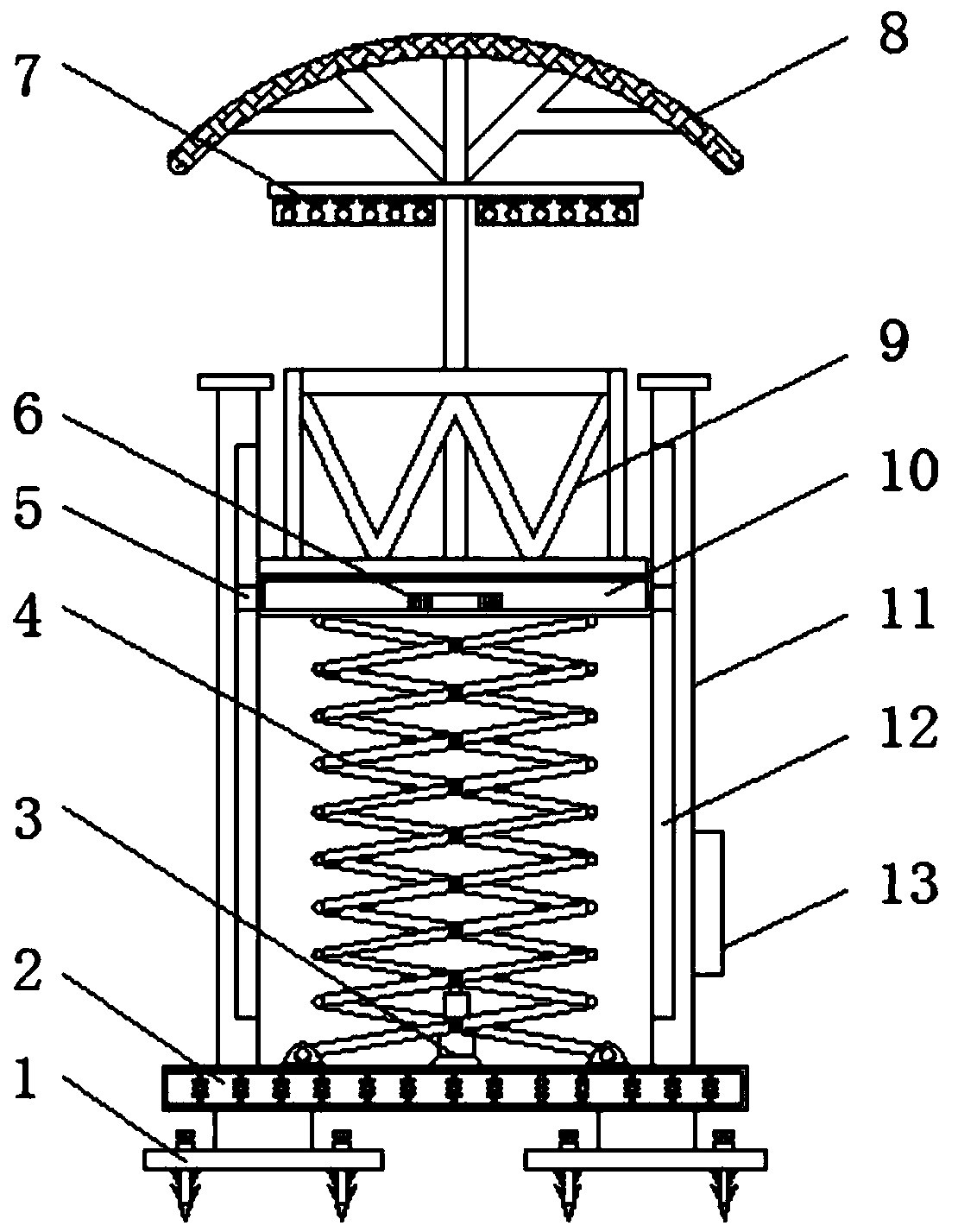
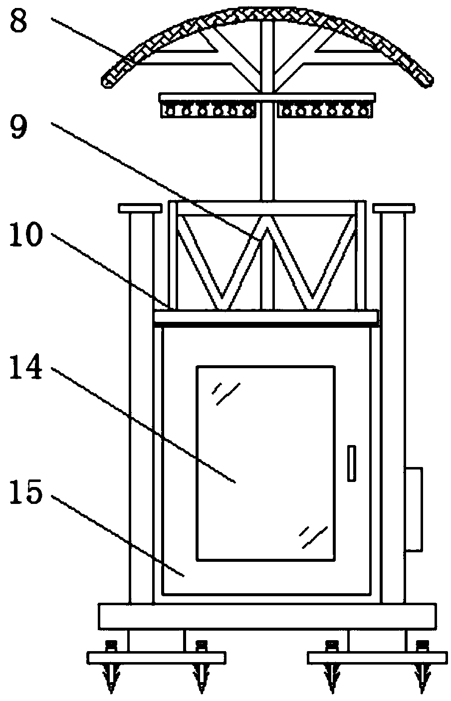
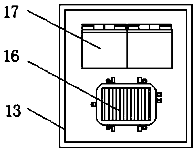
[0018] see Figure 1-4 , an embodiment provided by the present invention: a power equipment installation frame with automatic lifting function, including a base 2, a scissor frame 4, a solar panel 8 and a load plate 10, a tank 11 is installed on the top of the base 2, the base The inside of the base 2 is provided with a shock-absorbing layer, and the inside of the shock-absorbing layer is uniformly provided with a shock-absorbing spring, which is convenient fo...


PUM


Abstract

The invention discloses an electrical equipment mounting rack with an automatic lifting function. The electrical equipment mounting rack comprises a base, a scissor rack, a solar cell panel and a bearing plate. A slot body is formed in the top end of the base, and a control panel is arranged at one end of the slot body. A single chip microcomputer is arranged at one end of the inner part of the control panel, and a storage battery is arranged at the other end of the inner part of the control panel. A door body is arranged at the bottom end of one side of the slot body, the bottom end of the inner part of the slot body is hinged with the scissor rack, and the bearing plate is fixed arranged at the top end of the scissor rack. The solar cell panel is fixedly arranged at the center of the topof the bearing plate through a stand column, and the output end of the solar cell panel is electrically connected with the input end of the storage battery through a photovoltaic controller. The electrical equipment mounting rack is provided with a hydraulic telescopic rod and the scissor rack, and the top end of the scissor rack is connected with the bearing plate, so that the hydraulic telescopic rod is convenient to stretch out and draw back according to demands, therefore the height of the scissor rack is adjusted, and the automatic lifting of the bearing plate is realized.

Description

technical field [0001] The invention relates to the technical field of electric equipment installation auxiliary devices, in particular to an electric equipment installation frame with an automatic lifting function. Background technique [0002] Power equipment mainly includes power generation equipment and power supply equipment. Power generation equipment is mainly power plant boilers, steam turbines, gas turbines, water turbines, generators, transformers, etc. Power supply equipment is mainly transmission lines of various voltage levels, transformers, contactors, etc. Devices, etc., now for electrical equipment such as line towers and transformers located outdoors, workers generally perform fixed installation, which requires the use of mounting frames. [0003] However, most of the current mounting racks have simple structures and single functions, and have many limitations. Such devices are not equipped with guardrails, and the safety is not high. Workers are prone to ac...

Claims


Application Information

Patent Timeline
IPC IPC(8): B66F11/04B66F17/00F16F15/04H02B3/00
CPCB66F11/042B66F17/006F16F15/04H02B3/00
Inventor 吴昌飞
Owner WUHU SUNRISE NEW BUILDING MATERIALS TECH
Learn More