Light intensity distribution detection system

A detection system and technology of light intensity distribution, applied in photometry, optical radiation measurement, measurement devices, etc., can solve the problems of low sensitivity of thermal sensors, narrow light wave band, low resolution, etc., and achieve high sensitivity and high absorption rate. , high resolution and accuracy

Active Publication Date: 2020-07-10
TSINGHUA UNIV +1
View PDF3 Cites 0 Cited by
  • Summary
  • Abstract
  • Description
  • Claims
  • Application Information

AI Technical Summary

Problems solved by technology

Photon sensors have the advantages of high sensitivity and fast response speed. However, photon sensors require liquid nitrogen cooling, high cost, and narrow detectable light wave bands.
Thermal sensors are low cost, detectable in a wide band of light waves, and can operate at room temperature, however, thermal sensors have the disadvantages of low sensitivity and low resolution

Method used


Image

  • Light intensity distribution detection system
  • Light intensity distribution detection system
  • Light intensity distribution detection system

Examples


Embodiment Construction

[0031] The light intensity distribution detection system provided by the present invention will be further described in detail below in conjunction with the accompanying drawings and specific embodiments.

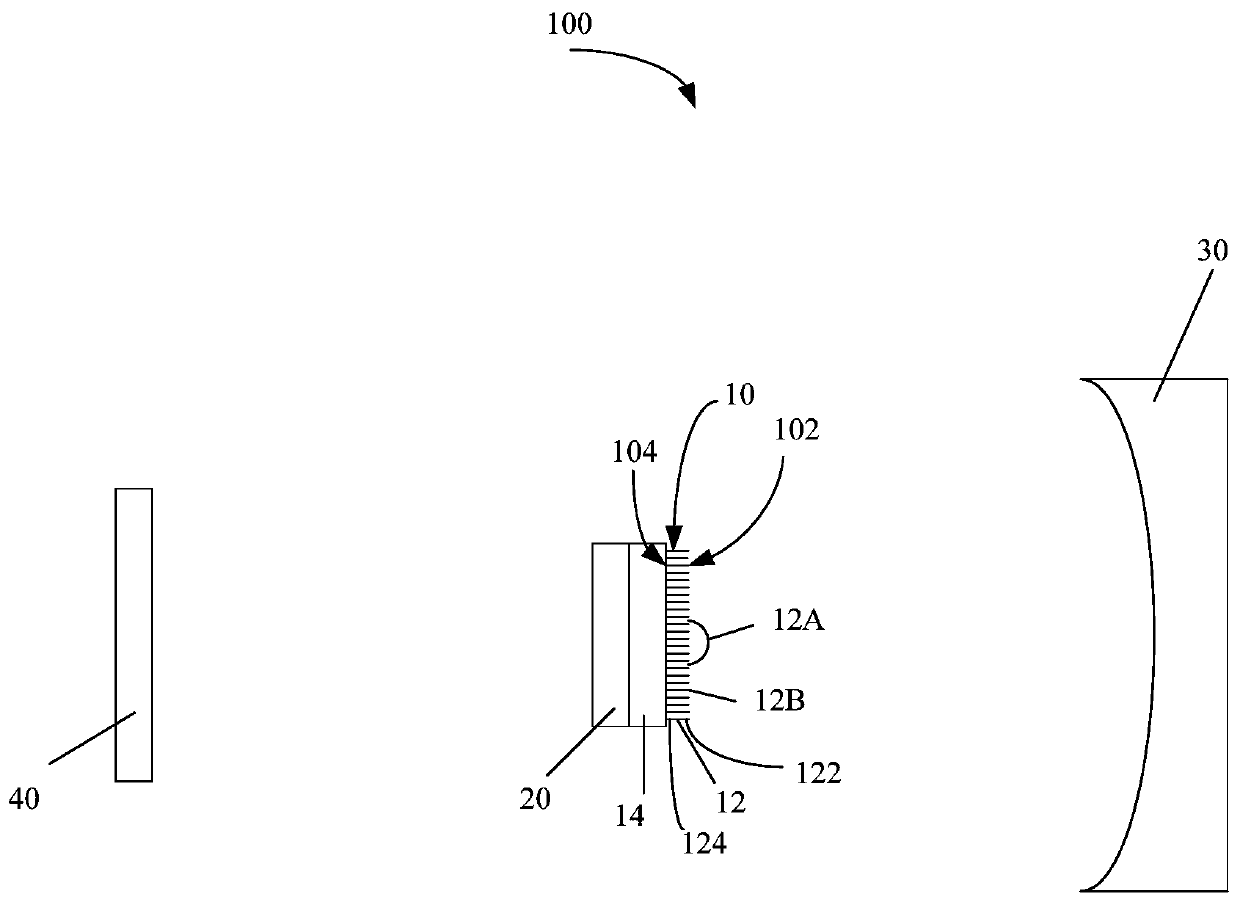
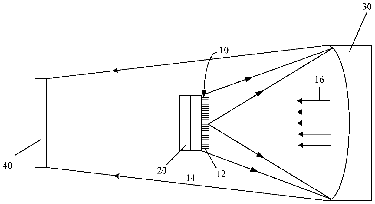
[0032] See figure 1 , the embodiment of the present invention provides a detection system 100 of light intensity distribution, comprising: a carbon nanotube array 10 disposed on the surface of a growth substrate, a cooling device 20 , a mirror 30 and an imaging element 40 . The cooling device 20 is arranged between the imaging element 40 and the growth substrate 14, and the cooling device is used to cool the growth substrate 14 so that the contact surface between the growth substrate 14 and the carbon nanotube array 10 maintains a constant temperature; The mirror 30 is spaced from the carbon nanotube array 10 , and the carbon nanotube array 10 is disposed between the mirror 30 and the growth substrate 14 ; the imaging element 40 is spaced from the cooling device 20 .

[00...


PUM

PropertyMeasurementUnit
diameteraaaaaaaaaa
diameteraaaaaaaaaa
diameteraaaaaaaaaa

Abstract

A light intensity distribution detection system includes a carbon nanotube array arranged on the surface of a growth substrate, a cooling device, a reflector and an imaging element. The cooling device is disposed between the growth substrate and the imaging element, and is used to cool the growth substrate so that the contact surface between the growth substrate and the carbon nanotube array maintains a constant temperature. The reflector is spaced apart from the carbon nanotube array, and the carbon nanotube array is disposed between the reflector and the substrate. The imaging element is spaced apart from the cooling device.

Description

technical field [0001] The invention relates to a detection system of light intensity distribution, in particular to a detection system of light intensity distribution based on a carbon nanotube array. Background technique [0002] The direction (angle) in which the light emitted by the light source propagates and the magnitude of its intensity are collectively referred to as "light intensity distribution". [0003] The measurement method of light intensity distribution is basically divided into two types: one is to place the sensor at a certain distance from the sample, and the sensor moves and measures at several points concentrically distributed around the sample to measure the distribution of light intensity; The other is to place the measuring device at different distances from the sample to measure the distribution of light intensity. The measuring device consists of a CCD sensor and an optical system with a super wide-angle prism similar to a fisheye lens. [0004] A...

Claims


Application Information

Patent Timeline
Patent Type & Authority Patents(China)
IPC IPC(8): G01J1/42
CPCG01J1/42G01J5/061G01J1/4257G01J1/0411G01J5/023G01J1/58G01J1/08G01J1/4228H01J37/26G01J1/0242G01J5/0853
Inventor 黄磊朱钧金国藩范守善
Owner TSINGHUA UNIV
Why Eureka
Try Eureka