Automatic adjusting device for optical lens and method thereof

An optical lens, automatic technology, applied in optics, optical components, instruments, etc., can solve the problems of difficult to guarantee accuracy, high cost, difficult technical promotion, etc., to improve assembly accuracy, eliminate lens center deviation error, and expand the scope of application Effect

Active Publication Date: 2018-11-02
BEIJING INSTITUTE OF TECHNOLOGYGY
View PDF7 Cites 18 Cited by
  • Summary
  • Abstract
  • Description
  • Claims
  • Application Information

AI Technical Summary

Problems solved by technology

However, this kind of double wedge optical path is actually difficult to adjust, and the accuracy is difficult to guarantee. The application range of this adjustment method is relatively limited, and it is difficult to carry out technical promotion
[0006] 2. Application number CN201611121714.3, the title of the invention is the installation and adjustment method based on catadioptric infrared imaging optical system, which discloses an installation and adjustment method based on catadioptric infrared imaging optical system, which solves the problem of existing infrared optical system installation and adjustment. The problem that the unit optical components cannot be quantified in the process can quickly, effectively and accurately realize the installation and adjustment of the catadioptric infrared imaging optical system
However, this method is only for infrared optical systems, and it is not universal for most optical systems, and there are many reflectors and transmission mirrors, and the internal optical system is relatively complicated, which greatly increases the cost of optical system installation and adjustment.
[000

Method used


Image

  • Automatic adjusting device for optical lens and method thereof
  • Automatic adjusting device for optical lens and method thereof
  • Automatic adjusting device for optical lens and method thereof

Examples


Embodiment Construction

[0043] The present invention will be described in detail below with reference to the figures and examples.

[0044] The invention provides an optical lens automatic adjusting device and method.

[0045] 1. The optical lens automatic adjustment device is as follows:

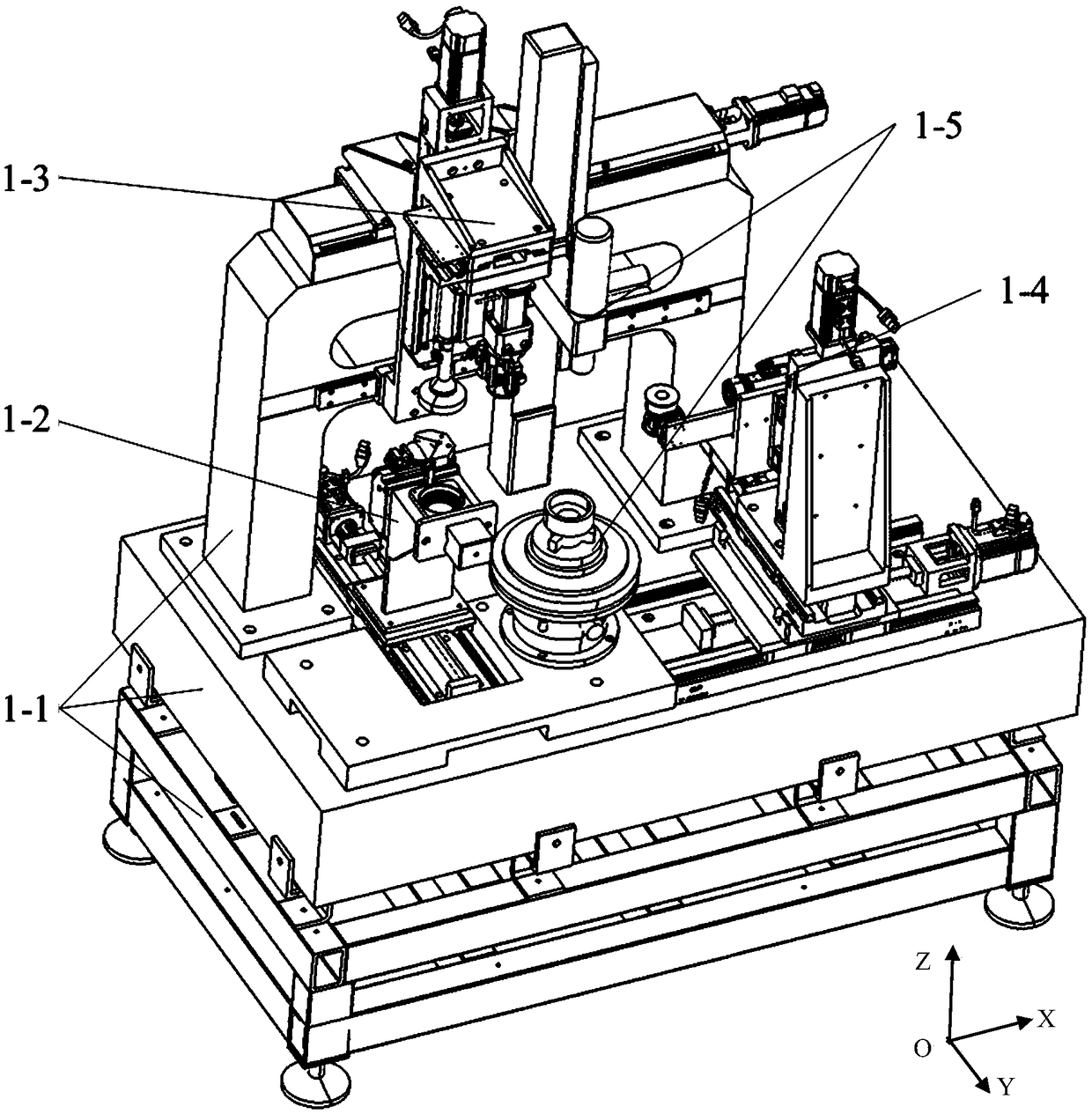
[0046] The structural diagram of the optical lens automatic assembly and adjustment device of the present invention is as followsfigure 1 shown. With the center of the plane where the device is located as the origin, establish the OXYZ coordinate system, define the OXY plane as the horizontal plane, and define the OXZ plane as the vertical plane. The optical lens automatic assembly and adjustment device of the present invention includes a control module, an auxiliary module 1-1, a feeding module 1-2, a clamping module 1-3, a coaxial alignment module 1-4 and an optical centering module 1-5, Under the control of the control module, the assembly and adjustment of the to-be-assembled part 2-5 and the lens barrel is ...


PUM


Abstract

The invention provides an automatic adjusting device for an optical lens and a method thereof, wherein the device can realize automatic clamping and centring adjustment of multiple optical devices. The automatic adjusting device for the optical lens has an aligning function and a centring adjusting function of the optical lens. The device comprises a holding member, a to-be-assembled member, a feeding module, a clamping module, a coaxial aligning module, an optical centring module and an auxiliary module. Through cooperation of each part, adjustment of a precise optical lens is finished, thereby realizing automatic assembling of an optical lens with multiple lenses and spacers. The modules can be used independently or together. An application range of precise optical component assembling is expanded. The automatic adjusting device for the optical lens has advantages of man-machine cooperation, and re-configuration. According to an adjusting method for the automatic adjusting device forthe optical lens, through a cross graticule, for aiming at an image which is formed by the lens on the CCD camera of an autocollimator, a lens central error and a lens interval are obtained. Throughpose adjustment, the lens central error is eliminated, and assembling precision between the lens and a lens barrel is further improved.

Description

technical field [0001] The invention relates to the field of optical system and electromechanical technology, in particular to an optical lens automatic assembly and adjustment device and method. Background technique [0002] With the rapid development of optical technology and the needs of people's production and life, the application fields of optical lenses are becoming wider and wider, ranging from aiming and positioning equipment in the aerospace field to camera lenses in the field of smartphones, optical lenses are ubiquitous. The optical performance of the optical lens largely depends on the adjustment accuracy of the optical lens. In order to ensure the optical resolution and precision, the adjustment of the optical lens must have high reliability. For the assembly and adjustment of precision optical lenses, most of the domestic still use traditional assembly and adjustment methods, relying on operators to perform manual adjustments. This method is clumsy, and the e...

Claims


Application Information

Patent Timeline
IPC IPC(8): G02B27/62
CPCG02B27/62
Inventor 叶鑫张之敬周登宇张恒金鑫赵一锦
Owner BEIJING INSTITUTE OF TECHNOLOGYGY
Why Eureka
Try Eureka