Method for estimating spatial rotation non cooperative target spindle based on vision SLAM (Simultaneous Localization And Mapping)

A non-cooperative target and space rotation technology, which is applied in the field of estimating the rotation axis of non-cooperative targets in space rotation, can solve the problems of poor accuracy, non-cooperative target recognition and detection, and non-consideration, so as to achieve the effect of improving accuracy and solving poor accuracy

A non-cooperative target and space rotation technology, which is applied in the field of estimating the rotation axis of non-cooperative targets in space rotation, can solve the problems of poor accuracy, non-cooperative target recognition and detection, and non-consideration, so as to achieve the effect of improving accuracy and solving poor accuracy

CN108734737AActive Publication Date: 2018-11-02HARBIN INST OF TECH

Image

  • Method for estimating spatial rotation non cooperative target spindle based on vision SLAM (Simultaneous Localization And Mapping)
  • Method for estimating spatial rotation non cooperative target spindle based on vision SLAM (Simultaneous Localization And Mapping)
  • Method for estimating spatial rotation non cooperative target spindle based on vision SLAM (Simultaneous Localization And Mapping)

Examples


specific Embodiment approach 1

[0061] Specific implementation mode 1: In this implementation mode, the specific process of estimating the rotation axis of a non-cooperative target in space rotation based on visual SLAM is as follows:

[0062] Step 1. Use the ImageNet database to pre-train the YOLO target detection model; input the non-cooperative target images obtained in the previous stage into the pre-trained YOLO target detection model for training, and obtain the trained YOLO target detection model;

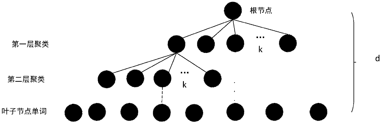
[0063] Step 2. Extract ORB feature points from the non-cooperative target image information obtained in the previous stage, and use the K-means algorithm to perform clustering to establish a k-cross number dictionary;

[0064] The specific process is:

[0065] Use the non-cooperative target rotation axis obtained in the early stage to build a dictionary to prepare for the subsequent loop detection;

[0066] The process of creating a dictionary is:

[0067] First, extract the ORB feature points from the n...

specific Embodiment approach 2

[0120] Specific embodiment 2: the difference between this embodiment and specific embodiment 1 is that in the first step, the ImageNet database is used to pre-train the YOLO target detection model; the non-cooperative target picture obtained in the previous stage is input into the pre-trained YOLO target detection The model is trained to obtain the trained YOLO target detection model; the specific process is:

[0121] The YOLO target detection model is a convolutional neural network, which includes 24 convolutional layers, 4 pooling layers and 2 fully connected layers, respectively:

[0122] 1 convolutional layer with a convolution kernel size of 7*7 and a number of 64;

[0123] 1 maximum pooling layer of 2*2;

[0124] 1 convolutional layer with a convolution kernel size of 3*3 and a number of 192;

[0125] 1 maximum pooling layer of 2*2;

[0126] 1 convolutional layer with a convolution kernel size of 1*1 and a number of 128;

[0127] 1 convolutional layer with a convolut...

specific Embodiment approach 3

[0143] Embodiment 3: This embodiment differs from Embodiment 1 or Embodiment 2 in that: the size of the obtained non-cooperation target pictures is 448Γ—448, the number of pictures is more than 800, and labels have been prepared.

[0144] Other steps and parameters are the same as those in Embodiment 1 or Embodiment 2.


PUM


Abstract

The invention discloses a method for estimating a spatial rotation non cooperative target spindle based on vision SLAM (Simultaneous Localization And Mapping), and relates to a method for estimating the spatial rotation non cooperative target spindle. In order to solve the problems of an existing method that estimation accuracy is poor, a calculation condition is restricted, interferences broughtsince other fragments are in the presence in a picture shot by a camera are not considered, and the estimation error of the rotation non cooperative target spindle is large, the method comprises the following steps that: 1: obtaining a trained YOLO target detection model; 2: establishing a k-ray tree dictionary; 3: estimating a per-frame rotation matrix and a translation matrix; 4: processing eachframe of image collected by a RGBD camera, and stopping collecting images by the RGBD (Red, Green and Blue-Depth) camera until a detection result shows that two-time loopback is obtained or appointedtime or frames are achieved; and 5: ensuring that the fit normal of a spatial plane is the slope of the non cooperative target spindle and the center of circle of a spatial circular arc is a point through which the non cooperative target spindle passes. The method is used for the field of spaceflight on-orbit service.

Description

technical field [0001] The invention relates to a method for estimating the rotational axis of a non-cooperative object in spatial rotation. This technology is applied in the field of aerospace on-orbit service. Background technique [0002] At present, countries around the world have launched various space vehicles, such as satellites, space shuttles, space stations and deep space probes, to explore and develop space. Among the more than 100 satellites launched every year in the world, 2-3 satellites are not normally put into orbit, and about 5 of the satellites that are correctly put into orbit will fail at the beginning of their life, and the failed satellites will also produce a lot of debris and space junk. Therefore, repairing or removing faulty or abandoned satellites in space has huge social and economic benefits and good application prospects. Unlike space stations, three-axis stable satellites and other cooperative targets whose motion status is known or can pro...

Claims


Application Information

Patent Timeline
02 Nov 2018
Publication
CN108734737A
IPC
G06T7/73
CPC
G06T7/73
Inventors
ηŽ‹ζŸ³; ιƒ­η»§ε³°