
An electret ultrasonic sputtering liquid charging device and charging method

A technology of a charging device and a charging method, which is applied in the direction of separation methods, combination devices, chemical instruments and methods, etc., can solve the problem of poor adaptability of multi-layer composite electrets, increased cost and complexity of process equipment, non-woven substrates, etc. To avoid problems such as the reduction of material strip power, to achieve a uniform and stable charging effect, a simple electret method, and to improve the uniformity of charging

Active Publication Date: 2021-05-14
JIANGSU YIMAO FILTER MEDIA CO LTD
View PDF8 Cites 0 Cited by
  • Summary
  • Abstract
  • Description
  • Claims
  • Application Information

AI Technical Summary

Problems solved by technology

[0003] Chinese Patent Publication No. CN1129963A, the date of publication is August 28, 1996, and the title of the invention is "Method for Charging Electret Filter Media". On the non-woven substrate, the non-woven substrate can capture a large amount of charge. This "spray charging" method works well for materials where short fibers account for more than 90% of the weight of the non-woven substrate, but it is not effective for long fibers. The impact force of the water column or water drop flow on the non-woven substrate is not enough, which reduces the charge of the non-woven substrate. In order to improve the filtration efficiency of the substrate, the pressure of the water column or water drop flow needs to be increased, which increases the cost and complexity of the process equipment.
One of the premise of this method is "to make the penetrating power of the liquid stronger and more uniform without damaging the substrate." For electrets with different thicknesses and different materials, it is more complicated and difficult to achieve the above prerequisites. , especially the poor adaptability to multi-layer composite electrets

Method used


Image

  • An electret ultrasonic sputtering liquid charging device and charging method

Examples


Embodiment 1

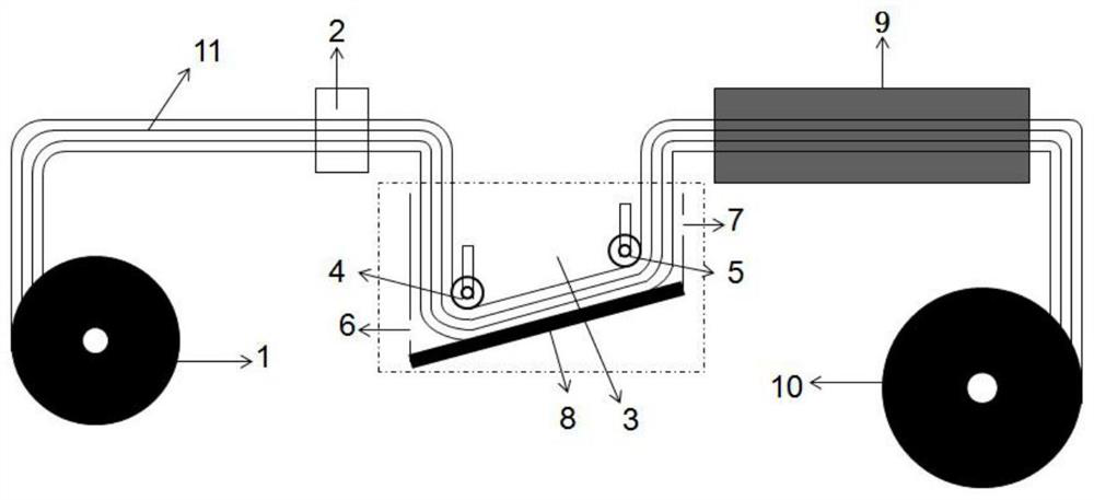
[0026] according to figure 1Schematic diagram of the electret ultrasonic sputtering liquid charging process, 50mm single-layer porous natural fiber sheet material, through the unwinding device at a line speed of 1m / min, first corona treatment through the corona device, tilted from 65° The lower end of the liquid tank tank enters the liquid tank equipped with deionized water. The distance between the first roller made of ceramics and the center line of the second roller made of ceramics is 2m. By adjusting the first roller made of ceramics, the ceramic The vertical distance between the second roller made and the bottom of the liquid tank is 50mm, so that the 50mm single-layer porous natural fiber sheet under the first roller made of ceramics is first passed through the second roller made of ceramics. The material is attached to the bottom of the liquid tank, and at the same time, an ultrasonic wave with a power of 5000w is applied to the bottom of the liquid tank filled with a ...

Embodiment 2

[0028] according to figure 1 It is a schematic diagram of the electret’s ultrasonic sputtering liquid charging process. The 0.5mm multi-layer porous chemical fiber sheet material passes through the unwinding device at a line speed of 10m / min, and first undergoes corona treatment through the corona device. From 20° The lower end of the inclined liquid tank enters the liquid tank equipped with ethanol. The distance between the first roller made of quartz and the center line of the second roller made of quartz is 0.5m. By adjusting the first roller made of quartz, the quartz The vertical distance between the second roller made and the bottom of the liquid tank is 0.5 mm, so that the first roller made of quartz passes through the bottom of the first roller made of quartz, and then the 0.5 mm multi-layer porous chemical layer is passed under the second roller made of quartz. The fiber material is attached to the bottom of the liquid tank, and at the same time, an ultrasonic wave wi...

Embodiment 3

[0030] according to figure 1 It is a schematic diagram of the ultrasonic sputtering liquid charging process of an electret. The polar liquid is a deionized water / ethanol mixture with a mass ratio of deionized water and ethanol of 30:70, and a mixture of 5mm multilayer porous natural fibers and chemical fibers. The sheet material, through the unwinding device at a linear speed of 50m / min, first undergoes corona treatment through the corona device, and enters the liquid tank filled with deionized water / ethanol mixture from the bottom of the 45° inclined liquid tank, quartz The distance between the first roller made of quartz and the center line of the second roller made of quartz is 1m, and the vertical distance between the first roller made of quartz and the second roller made of quartz and the bottom of the liquid tank is 5mm , so that the 5mm multi-layer porous natural fiber and chemical fiber mixed sheet material under the first roller made of quartz and then the second roll...


PUM

PropertyMeasurementUnit
thicknessaaaaaaaaaa

Abstract

The invention discloses an electret ultrasonic sputtering liquid charging device and a charging method. In the ultrasonic sputtering charging device of the electret, the liquid tank is trapezoidal, the bottom of the liquid tank and the horizontal plane form an angle of 20-65°, and the material that can be electret enters from the bottom of the liquid tank through the unwinding device. The liquid tank, through the first roller shaft and the second roller shaft, the electret material can be attached to the bottom of the liquid tank, and at the same time, ultrasonic waves can be applied to the bottom of the liquid tank filled with polar liquid and materials that can be electret. After the electret material leaves the liquid tank, it is dried by a drying device to obtain a charged electret. This method can adjust the distance between the first roller shaft, the second roller shaft and the bottom of the liquid tank, and change the inclination of the bottom of the liquid tank, so that the electret materials with different thicknesses and different materials can be laminated easily. , Efficient, stable and uniform charging.

Description

technical field [0001] The invention relates to an electret liquid charging device and a charging method, in particular to an electret ultrasonic sputtering liquid device and a charging method. Background technique [0002] Traditional air filter materials mainly rely on physical and mechanical effects such as Brownian diffusion, entrapment effect, inertial collision, and natural gravity sedimentation to block particles in the air. At present, in the field of air filter materials, the pursuit of high efficiency and low resistance of materials, and the air filter materials that can achieve high efficiency and low resistance are almost all made of electret materials. The material after electret treatment is used for air filtration. In addition to physical and mechanical functions, it also has electrostatic adsorption. Under the premise of ensuring the same filtration efficiency, the pore size of the electret filter material can be larger than that of ordinary filter materials...

Claims


Application Information

Patent Timeline
Patent Type & Authority Patents(China)
IPC IPC(8): B01D39/00B01D50/00
CPCB01D39/00B01D50/00B01D2239/0435B01D2239/10
Inventor 张科王亚飞吴龙涛张小宇陈太照林勇宋宝祥沈艳王平刘欣顾绍金邓波
Owner JIANGSU YIMAO FILTER MEDIA CO LTD
Learn More