Thread machining device for screw

A thread processing and screw technology, which is applied in the field of screw processing, can solve problems such as the inability to prevent defective screws from being transferred into the collection container, the single specification of processed screws, and inconvenient operation and use, and achieve a wide range of use, convenient operation, and simple structure. Effect

Pending Publication Date: 2018-11-06
无锡市钰汌工贸有限公司
View PDF0 Cites 0 Cited by
  • Summary
  • Abstract
  • Description
  • Claims
  • Application Information

AI Technical Summary

Problems solved by technology

[0003] However, the existing thread processing devices generally have a complicated structure and are inconvenient to operate and use. The specifications of the processing screws are relatively single, which reduces the scope of use. Some thread processing devices have a fixed helix angle for processing threads, which has great limitations. Sexuality, affecting production needs, and some thread processing devices cannot prevent defective screws from being transferred into the collection container during processing. Due to the small size and large number of screws, it is difficult to screen out these defective products, which increases the difficulty of inspection and affects the product. pass rate, which is far from meeting the current people's requirements for this product

Method used


Image

  • Thread machining device for screw
  • Thread machining device for screw
  • Thread machining device for screw

Examples


Embodiment Construction

[0017] The following will clearly and completely describe the technical solutions in the embodiments of the present invention with reference to the accompanying drawings in the embodiments of the present invention. Obviously, the described embodiments are only some, not all, embodiments of the present invention. Based on the embodiments of the present invention, all other embodiments obtained by persons of ordinary skill in the art without making creative efforts belong to the protection scope of the present invention.

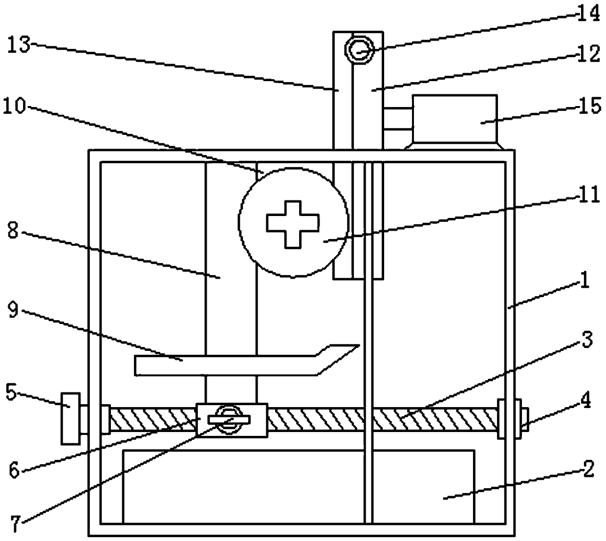
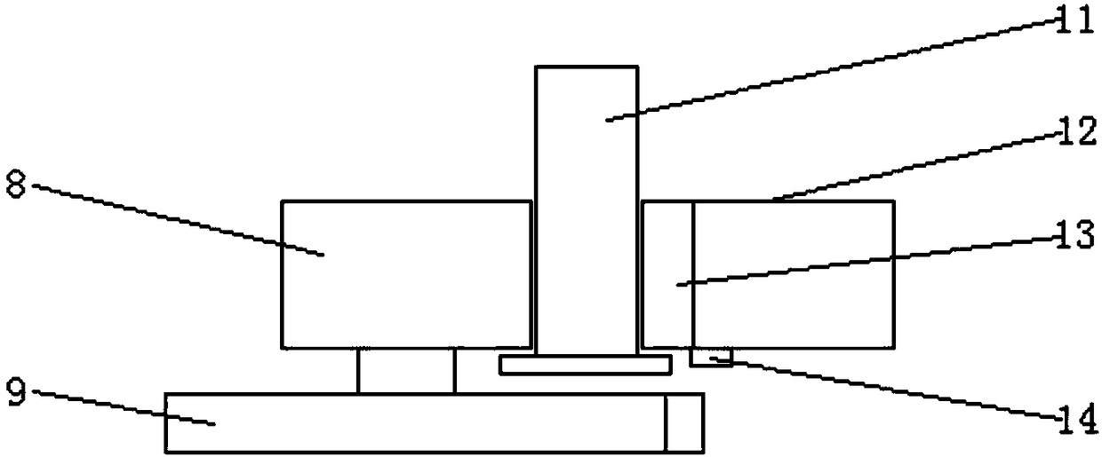
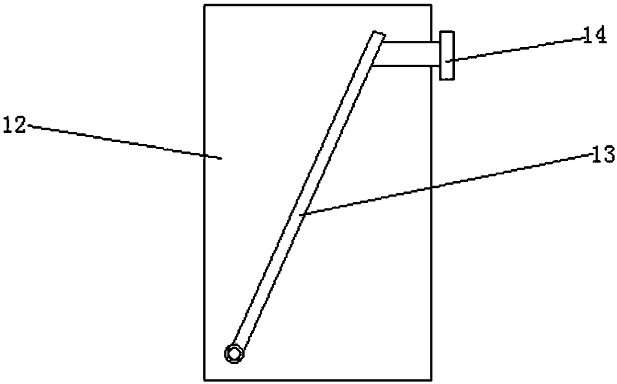
[0018] see Figure 1-Figure 3 , the present invention provides a technical solution: a thread processing device for screws, including a frame 1, a collection box 2 is provided at the bottom of the frame 1, a lead screw 3 is provided above the collection box 2, and the lead screw 3 Both ends are fitted with bearings 4, and the bearings 4 are fixedly connected to both sides of the frame 1, the left end of the screw 3 is screwed to an adjusting nut 5, and the rig...


PUM


Abstract

The invention discloses a thread machining device for a screw. The thread machining device for the screw comprises a rack, wherein a collecting box is arranged at the bottom of the rack; a lead screwis arranged above the collecting box; bearings are mounted at two ends of the lead screw in a sleeving mode, and the bearings are fixedly connected to two sides of the rack; the left end of the lead screw is in threaded connection to an adjusting nut; a sliding block is arranged on the right side of the adjusting nut, and the sliding block is mounted on the outer side of the lead screw in a sleeving mode; a fixed bolt is connected to the outer side of the sliding block; a thread rolling fixed plate is perpendicularly arranged above the fixed bolt, and is fixedly connected to the top of the sliding block; a malposition-preventing baffle plate is welded to the outer side of the thread rolling fixed plate horizontally; a thread rolling groove is formed in the inner side of the malposition-preventing baffle plate; and the screw is arranged in the thread rolling groove. The thread machining device for the screw disclosed by the invention is simple in structure, convenient to operate and wide in application range, and can machine threads of different specifications and screen defective products, so that the percent of pass is improved. The thread machining device for the screw has a wideapplication prospect.

Description

technical field [0001] The invention relates to the field of screw processing, in particular to a screw thread processing device. Background technique [0002] With the advancement of science and technology and the development of production technology, more and more automation equipment has been put into the production line. Automation operations have replaced manual simple and repetitive assembly line operations, which can effectively improve the productivity and competitiveness of enterprises. In industries such as furniture manufacturing and furniture manufacturing, screw assembly operations are widely used. Thread processing uses tools for making threads, and processes workpieces by cutting, turning, milling, grinding, etc., so that the screws have threads of specific shapes. Thread cutting is generally Refers to the method of machining threads on workpieces with forming tools or grinding tools. When machining threads, the tool and workpiece make relative rotational move...

Claims


Application Information

Patent Timeline
IPC IPC(8): B23G9/00
CPCB23G9/001
Inventor 刘学庆
Owner 无锡市钰汌工贸有限公司
Why Eureka
Try Eureka