Laser eutectic welding device and application method

A eutectic welding and laser technology, applied in the field of optical modules, can solve the problem of easy oxidation of the laser carrier

Inactive Publication Date: 2018-11-06
HISENSE BROADBAND MULTIMEDIA TECH
View PDF6 Cites 3 Cited by
  • Summary
  • Abstract
  • Description
  • Claims
  • Application Information

AI Technical Summary

Problems solved by technology

[0005] The invention provides a laser eutectic welding device and its use method to solve the problem that th

Method used


Image

  • Laser eutectic welding device and application method
  • Laser eutectic welding device and application method
  • Laser eutectic welding device and application method

Examples


Example Embodiment

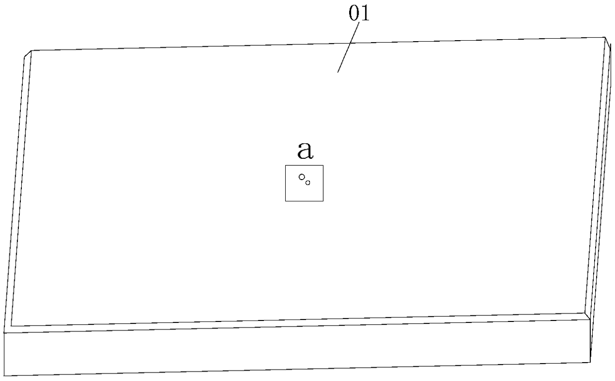
[0037] In the prior related art, a vacuum hole is provided on the upper surface of the tray in the laser eutectic welding device, and an electric heating wire is provided inside the laser carrier tray. When the laser carrier tray is used to position the laser carrier, the laser carrier is placed at the vacuum hole, and the laser carrier is adsorbed by the vacuum negative pressure at the vacuum hole, thereby realizing the positioning of the laser carrier. Since the laser carrier is positioned on the laser carrier tray through the vacuum hole, during the process of placing the laser on the laser carrier, the laser carrier will shift due to uneven force, thereby reducing the lamination accuracy of the laser and the laser carrier. In addition, after the laser is placed on the laser carrier, the electric heating wire starts to heat the laser carrier tray, and then heats the laser carrier, and finally realizes the welding of the laser and the laser carrier tray. However, due to the ...


PUM


Abstract

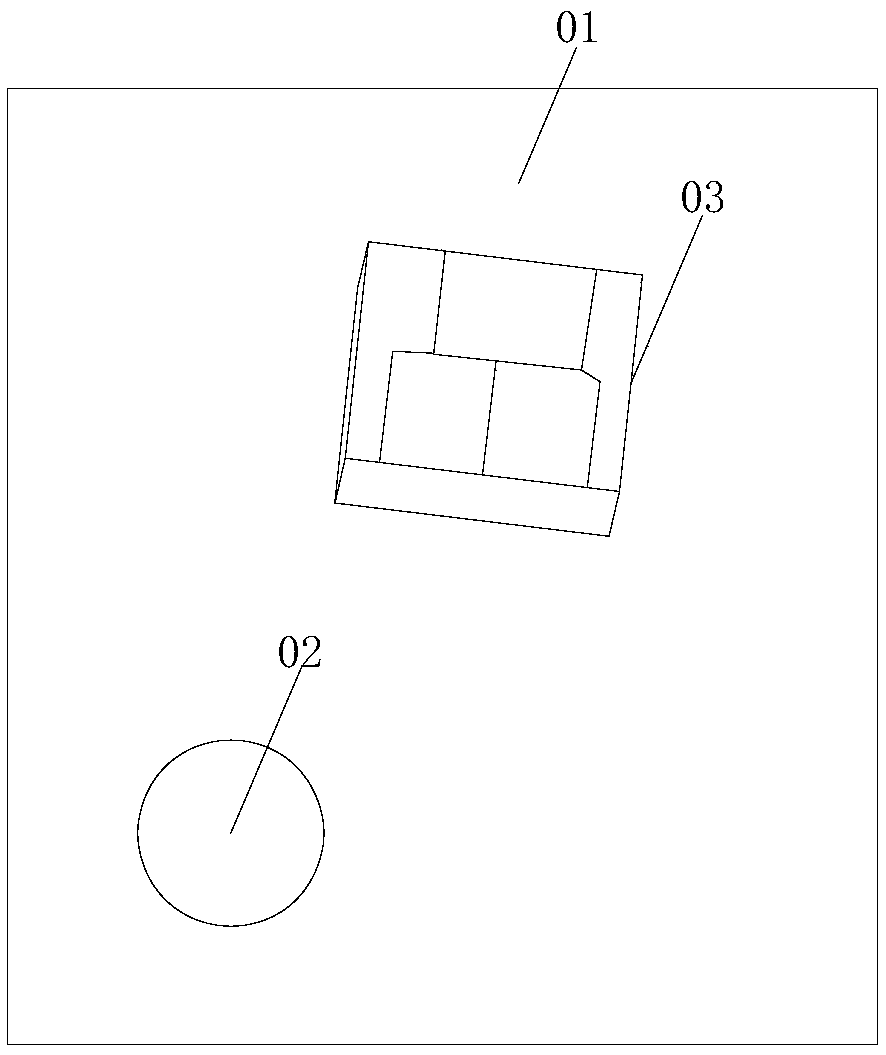
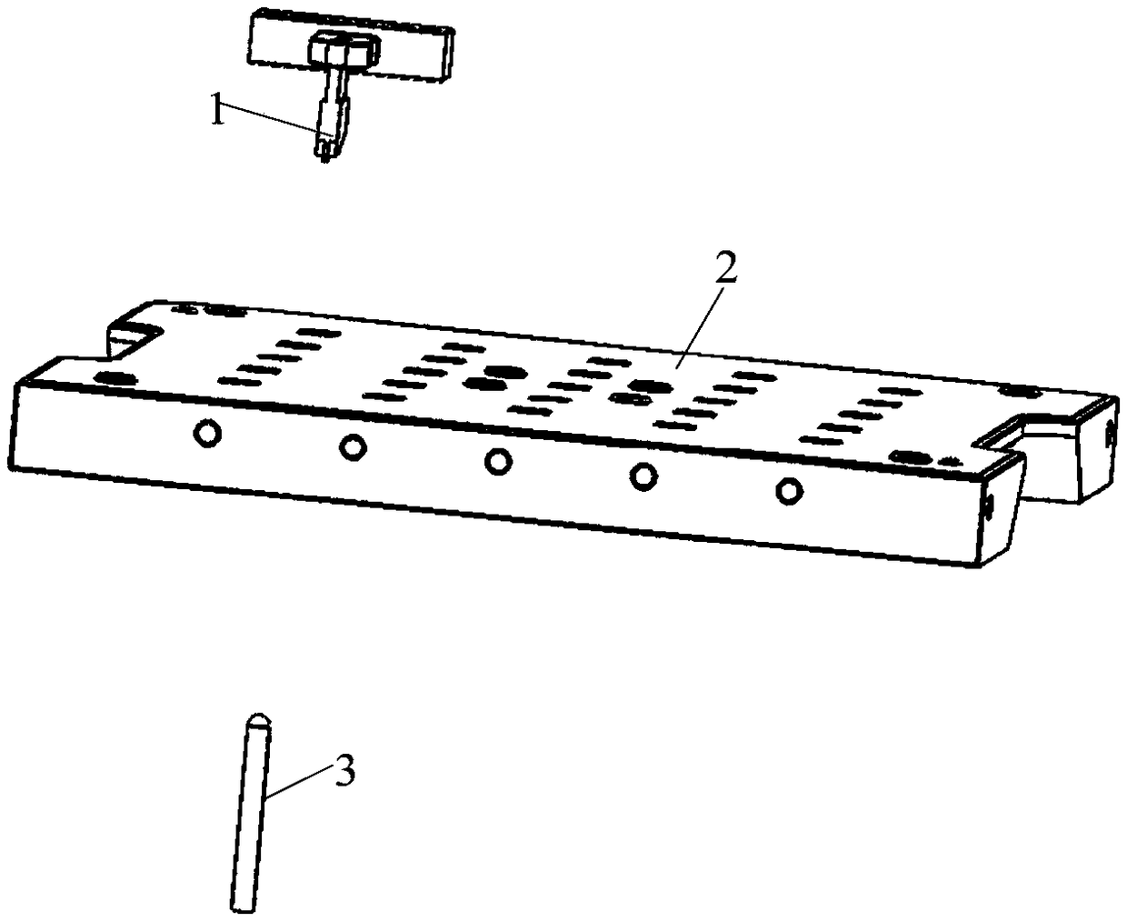
The invention provides a laser eutectic welding device and an application method. The device comprises a laser absorbing part, a laser carrier tray and a laser heater. A through hole and a vacuum holein the laser absorbing part is arranged, so that the machining difficulty of an internal micro vacuum hole can be reduced, the inclination side surface of the laser absorbing part enables image scanning equipment to directly identify the position of the laser, and the precision of a paster is improved. In the laser carrier tray, the circulation of laser transmission and negative pressure air is achieved through the vacuum suction hole and the through hole, and the aperture of the through hole is larger than the aperture of the vacuum suction hole, so that the processing difficulty of the micro vacuum suction hole can be reduced, and the passing rate of the laser can be improved. Laser emitted by the laser heater penetrates through a light-transmitting glass sheet and the through hole, andthe laser through hole and the vacuum suction hole are directly irradiated on a laser carrier, so that direct heating of the laser carrier is realized, the heating speed and the cooling speed of thelaser carrier are high, the energy consumption is low, the oxidation speed of the laser carrier is reduced, and the welding quality is improved.

Description

technical field [0001] The invention relates to the technical field of optical modules, in particular to a laser eutectic welding device and a method of use. Background technique [0002] The optical module is a component that realizes photoelectric conversion, that is, the transmitting end converts the electrical signal into an optical signal and transmits it through an optical fiber; the receiving end converts the received optical signal into an electrical signal. In the composition of the optical module, the laser is the light source component of the optical module and is used to generate laser light. When the optical module is assembled, the laser is usually welded on the laser carrier, so that the laser carrier can be packaged in the optical module by arranging the laser carrier in the box of the optical module. [0003] For the welding of the laser on the laser carrier, the laser carrier is usually placed on a tray with a heating function, and the laser carrier is pos...

Claims


Application Information

Patent Timeline
IPC IPC(8): B23K26/21B23K26/70
CPCB23K26/21B23K26/70B23K26/702
Inventor 杜光超唐永正
Owner HISENSE BROADBAND MULTIMEDIA TECH
Why Eureka
Try Eureka