
Prefabricated energy dissipation and damping beam-column joint for prestressed concrete frame

A prefabricated beam and concrete technology, applied in earthquake resistance, building types, buildings, etc., can solve the problems of concrete damage at the beam-column interface, insufficient energy dissipation capacity, etc. Effect

Pending Publication Date: 2018-11-06
DALIAN UNIV OF TECH +2
View PDF0 Cites 2 Cited by
  • Summary
  • Abstract
  • Description
  • Claims
  • Application Information

AI Technical Summary

Problems solved by technology

However, the traditional unbonded post-tensioned prestressed concrete frame joints have problems such as insufficient energy dissipation capacity and serious damage to the concrete at the beam-column interface.

Method used


Image

  • Prefabricated energy dissipation and damping beam-column joint for prestressed concrete frame
  • Prefabricated energy dissipation and damping beam-column joint for prestressed concrete frame
  • Prefabricated energy dissipation and damping beam-column joint for prestressed concrete frame

Examples


Embodiment 1

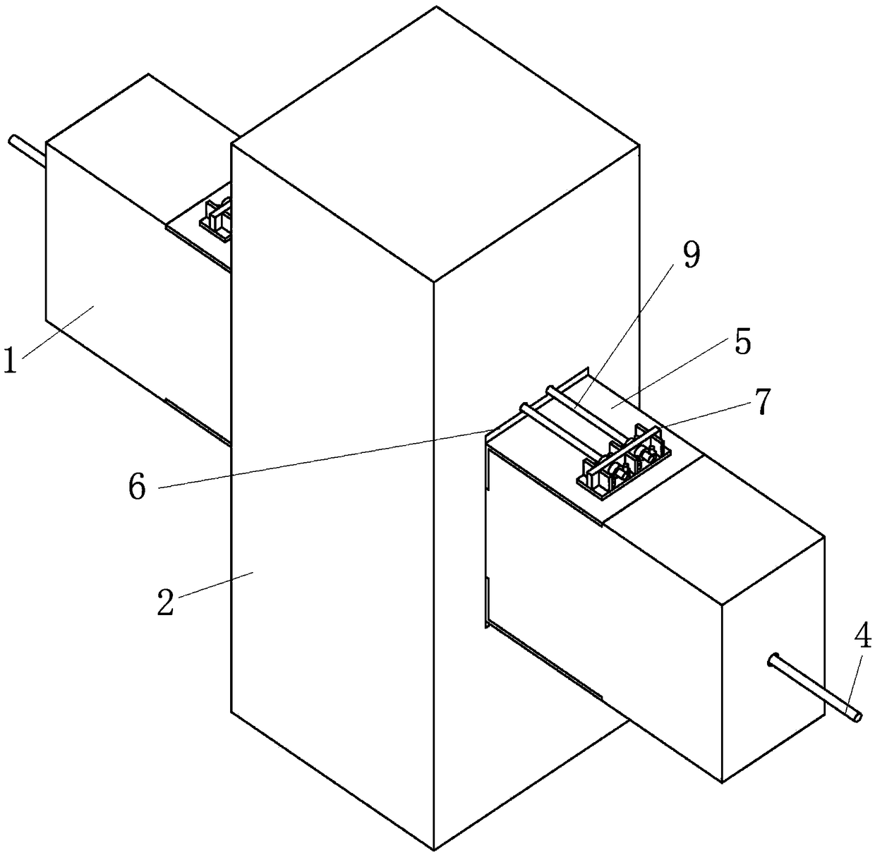
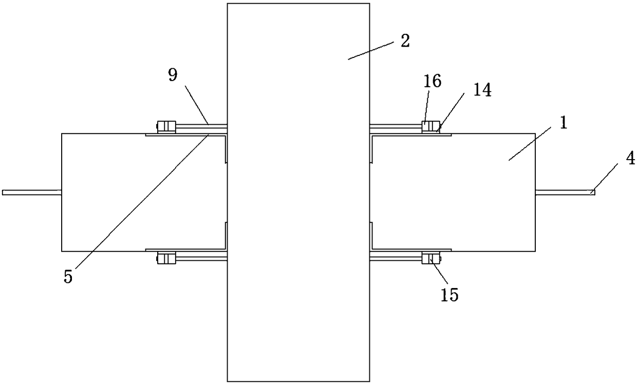
[0045] Such as Figure 1-Figure 6 As shown, a prefabricated prestressed concrete frame energy-dissipating and shock-absorbing beam-column joint, including:

[0046] Along the axis of the prefabricated beam 1, the prestressed steel strand reserved channel 3 of the interconnected prefabricated beam 1 and prefabricated column 2 is provided. The steel strand 4 is connected by grouting between the prestressed steel strand 4 located in the middle of the prefabricated beam 1 and the prestressed steel strand reserved tunnel 3;

[0047] Angle steels 5 are pre-embedded at the upper and lower corners of both ends of the prefabricated beam 1, and reinforced steel plates 6 corresponding to the angle steels 5 are pre-embedded on the prefabricated column 2;

[0048] The angle steel support plate of the angle steel 5 perpendicular to the prefabricated column 2 is provided with an energy-dissipating steel bar joint 7, and the prefabricated column 2 is provided with two penetrating prefabricat...

Embodiment 2

[0062] Such as Figure 7 As shown, a prefabricated prestressed concrete frame energy-dissipating and shock-absorbing beam-column node differs from Embodiment 1 in that the interconnected prefabricated beam 1 and prefabricated column 2 include a prefabricated column 2 and a prefabricated beam 1, so The fixing device is a fixed steel plate 20 embedded in the prefabricated column 2 corresponding to the reinforced steel plate 6, and the energy-dissipating steel rod 9 passes through the fixed steel plate 20 and connects to the fixed steel plate through a fixed bolt 21. 20 connections.


PUM


Abstract

The invention discloses a prefabricated energy dissipation and damping beam-column joint for a prestressed concrete frame. Angle steel is pre-buried in the upper corners and the lower corners of the two ends of a prefabricated beam, and a reinforcing steel plate corresponding to the angle steel is pre-buried in a prefabricated column; energy dissipation steel bar connectors are arranged on an angle steel supporting plate, perpendicular to the prefabricated column, of the angle steel, and a plurality of energy dissipation steel bar reserved hole passages penetrating through the prefabricated column in the extending direction of the prefabricated beam and corresponding to the energy dissipation steel bar connectors are formed in the prefabricated column; energy dissipation steel bars are arranged in the energy dissipation steel bar reserved hole passages, one ends of the energy dissipation steel bars are connected with the energy dissipation steel bar connectors, and the other ends of the energy dissipation steel bars penetrate out of the prefabricated column to be fixedly connected with a fixing device; and the energy dissipation steel bars and the energy dissipation steel bar reserved hole passages are connected through grout. The prefabricated energy dissipation and damping beam-column joint has the characteristics of being simple in structure, stable in property, practical and effective, damping can be increased to a large extent, and damage to concrete of the beam-column joint is relieved.

Description

technical field [0001] The invention relates to the technical field of energy-dissipating and shock-absorbing passive control of building structures, in particular to a prefabricated prestressed concrete frame energy-dissipating and shock-absorbing beam-column node. Background technique [0002] Earthquakes are frequent natural disasters around the world. Once they occur, they often cause immeasurable damage and bring huge losses to life and property safety. For concrete frame structures, the safety of joints is the focus of earthquake resistance. [0003] Prefabricated concrete structures have the advantages of convenient construction, environmental protection and energy saving, and have been widely recognized and widely used at home and abroad. However, compared with cast-in-place concrete structures, prefabricated concrete structures have the problem of poor node reliability. Therefore, the key to precast concrete structures is the nodes. The quality and performance of t...

Claims


Application Information

Patent Timeline
IPC IPC(8): E04B1/22E04B1/21E04B1/98E04H9/02
CPCE04B1/21E04B1/215E04B1/22E04H9/021E04H9/025Y02A30/30
Inventor 柯善杰何政杜彬潘峰黄国辉
Owner DALIAN UNIV OF TECH
Learn More