
A three-dimensional shape measurement method and device based on optical fringe projection and reflection

A fringe projection, three-dimensional topography technology, applied in measurement devices, optical devices, instruments, etc., can solve the problem of poor integration, inability to obtain three-dimensional topography, and inability to achieve simultaneous and non-limited measurement of objects with diffuse and specular reflection properties. and other problems, to achieve the effect of cost saving, easy promotion, and improvement of measurement efficiency

Active Publication Date: 2019-12-10
HEBEI UNIV OF TECH
View PDF7 Cites 0 Cited by
  • Summary
  • Abstract
  • Description
  • Claims
  • Application Information

AI Technical Summary

Problems solved by technology

[0009] In summary, although the above-mentioned existing 3D measurement technologies based on optical fringe projection and reflection all have the advantages of non-contact, full-field and fast measurement, they are also continuing to develop in the direction of large dynamic range, fast and high-precision measurement. , but neither can realize the simultaneous and non-limited measurement of diffuse reflection and specular reflection objects, and the integration is poor
Especially with the development of advanced manufacturing and intelligent manufacturing technology, objects with a combination of diffuse reflection and specular reflection characteristics often appear, and the existing optical measurement methods cannot obtain the three-dimensional shape of such combined objects

Method used


Image

  • A three-dimensional shape measurement method and device based on optical fringe projection and reflection
  • A three-dimensional shape measurement method and device based on optical fringe projection and reflection
  • A three-dimensional shape measurement method and device based on optical fringe projection and reflection

Examples


Embodiment Construction

[0044] Specific examples of the present invention are given below. The specific embodiments are only used to further describe the present invention in detail, and do not limit the protection scope of the claims of the present application.

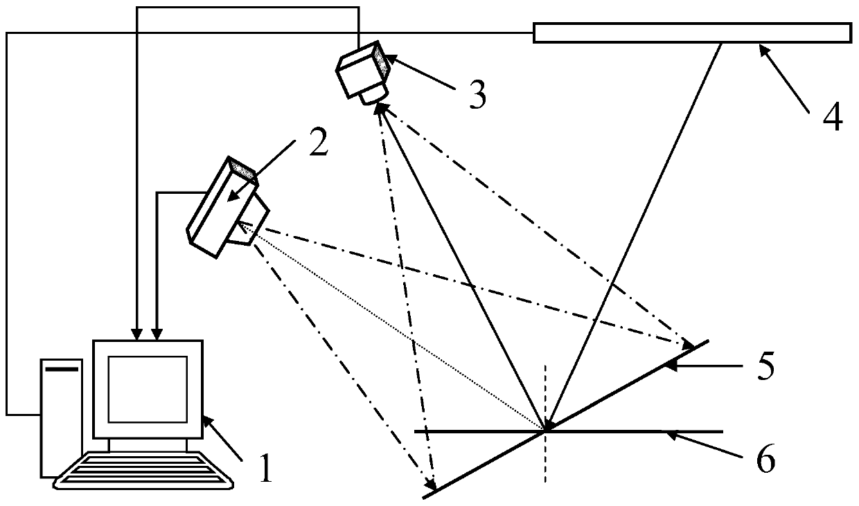
[0045] The invention provides a three-dimensional shape measurement device based on optical fringe projection and reflection (see figure 1 , referred to as the device), it is characterized in that the device includes a computer 1, a visible light projector (abbreviated as the projector) 2, a CCD color camera (referred to as the camera) 3, a display screen 4, a diffuse reflection object fixture 5 to be measured and a specular reflector to be measured The object fixing device 6; the projector 2, the camera 3 and the diffuse reflection object to be measured constitute a diffuse reflection measurement system; the display screen 4, the camera 3 and the specular reflection object to be measured constitute a specular reflection measurement system;...


PUM


Abstract

The invention discloses a three-dimensional morphology measurement method based on optical strip projection and reflection and a device. The device comprises a computer, a visible light projector, a CCD (Charge Coupled Device) colorful camera, a display screen, a to-be-tested diffuse reflection object fixing device and a to-be-tested mirror surface reflection object fixing device, wherein the computer is connected with the projector, the camera and the display screen; the projector and the camera are mounted on an optical platform; the display screen is fixed on a precise horizontal movement platform of the optical platform; the projector, the camera and the display screen are positioned on the same side; the camera is positioned between the projector and the display; the to-be-tested diffuse reflection object fixing device and the to-be-tested mirror surface reflection object fixing device are placed on the optical platform; acute angles are formed between the optical axis of the camera and a normal vector of a plane of the display screen and between the optical axis of the camera and the optical axis of the projector. By adopting the method, both a diffuse reflection object and amirror surface reflection object can be measured and objects of two reflection properties can be simultaneously measured, and flexible measurement and integration measurement can be achieved.

Description

technical field [0001] The invention relates to the field of three-dimensional shape measurement, in particular to a three-dimensional shape measurement method and device based on optical fringe projection and reflection. Background technique [0002] The optical three-dimensional shape measurement method is widely used in industrial online inspection, virtual reality, cultural relics protection, reverse engineering, biomedicine and other fields due to its advantages of non-contact, fast measurement speed and non-destructiveness. According to the reflection properties of the measured object, optical three-dimensional measurement is mainly divided into three-dimensional shape measurement of diffuse reflection and specular reflection. At present, the measurement of these two kinds of reflective objects is mostly studied separately, the experimental system is built separately, and the measurement is carried out separately. With the advancement of science and technology and the...

Claims


Application Information

Patent Timeline
Patent Type & Authority Patents(China)
IPC IPC(8): G01B11/25
CPCG01B11/254
Inventor 张宗华刘小红高楠
Owner HEBEI UNIV OF TECH
Learn More