Grass density detecting device and mower

A technology for detecting devices and density, which is applied to measuring devices, harvesters, and mechanical devices, etc., can solve the problems of high cost, large error in optical recognition, and lack of widespread popularization, so as to achieve accurate measurement and increase friction , the effect of reducing energy consumption

Pending Publication Date: 2018-11-06
ZHEJIANG YAT ELECTRICAL APPLIANCE CO LTD
View PDF0 Cites 5 Cited by
  • Summary
  • Abstract
  • Description
  • Claims
  • Application Information

AI Technical Summary

Problems solved by technology

The existing detection of grass density is carried out through optical recognition. Due to the large error and high cost of optical recognition, it has not been widely popularized.

Method used


Image

  • Grass density detecting device and mower
  • Grass density detecting device and mower
  • Grass density detecting device and mower

Examples


Embodiment 1

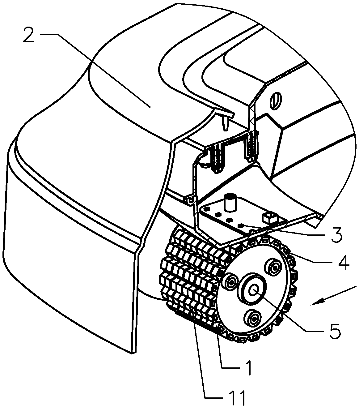
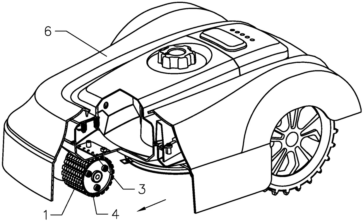
[0031] like figure 1 and figure 2 As shown, the present invention provides a kind of grass density detection device, which is installed on the mobile body 2. The grass density detection device includes a roller 1, which is connected in rotation with the mobile body 2, and the axis of the roller 1 is perpendicular to the mobile body. 2's movement direction setting, figure 1 The direction indicated by the middle arrow is the moving direction of the moving body 2. The circumferential surface of the roller 1 is not in contact with the ground but is in contact with the grass. Because the roller 1 moves with the moving body 2, the grass will generate friction on the roller 1 after the roller 1 contacts the grass. The grass density detection device also includes a speed measuring mechanism for detecting the real-time rotation speed of the roller 1. By measuring the real-time rotation speed of the roller 1, the friction force of the grass acting on the roller 1 can be known to deter...

Embodiment 2

[0047] The main difference between this embodiment and Embodiment 1 is that the speed measuring mechanism includes a photoelectric sensor.

[0048] The speed measuring mechanism includes a photoelectric sensor, and the circumferential surface of the roller is coated with white paint and black paint at intervals. The advantage of this setting is that the white pigment and black pigment make the reflected light and non-reflected light appear alternately, and the photoelectric sensor receives the reflected light signal at intervals accordingly, and outputs intermittent electrical signals, and the real-time rotation speed of the roller can be obtained according to the electrical signals. Know the frictional force of the grass on the roller to judge the density of the grass. Due to the high measurement accuracy and fast response of the photoelectric sensor, the results obtained are more accurate.

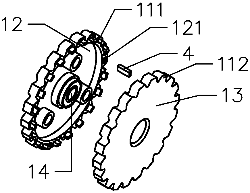
[0049] It can be understood that a plurality of reflective plates can also be unifo...


PUM


Abstract

The invention provides a grass density detecting device and a mower. The grass density detecting device is installed on a moving body. The grass density detecting device comprises a roller and a speedmeasuring mechanism that are rotatingly connected to the moving body. The axis of the roller is perpendicular to the moving direction of the moving body. The circumferential surface of the roller does not contact with the ground but contacts with the grass. The roller moves along with the moving body. A friction force between the roller and the grass is generated. The speed measuring mechanism can measure the real-time rotation speed of the roller, thus the friction force of the grass on the roller can be calculated, and the grass density can be judged. The grass density is calculated and judged by the program without artificial intervention, the detection error is reduced, the measurement is precise, at the same time, the automation degree of grass density detection is improved, the workload is reduced, the work strategy can be adjusted based on measured grass density, a work strategy with low work strength is adopted, and the energy consumption is reduced.

Description

technical field [0001] The invention relates to the technical field of lawnmowers, in particular to a grass density detection device and a lawnmower. Background technique [0002] In recent years, with the improvement of people's awareness of environmental protection, the area of ​​green space in cities has increased day by day, and the workload of daily maintenance of lawns has become increasingly heavy. In order to improve the working efficiency of lawn mowers and reduce the workload of maintaining lawns, according to The degree of density adjusts the working strategy of the mower in real time. Existing detection of grass density is carried out by means of optical recognition. Due to large errors in optical recognition and high cost, it has not been widely popularized. Contents of the invention [0003] The object of the present invention is to provide a grass density detection device and a lawn mower with accurate measurement. [0004] In order to achieve the above ob...

Claims


Application Information

Patent Timeline
Patent Type & Authority Applications(China)
IPC IPC(8): G01N19/00G01N19/02G01P3/36A01D34/00
CPCG01N19/00A01D34/006G01N19/02G01P3/36
Inventor 马顺杰李鹏张进
Owner ZHEJIANG YAT ELECTRICAL APPLIANCE CO LTD
Why Eureka
Try Eureka