
Method for manufacturing spliced large-caliber photon sieve

A production method and technology of photon sieves, applied in the field of optics, can solve problems such as splicing errors and photon sieve resolution reduction, so as to reduce the difficulty of splicing and ensure the image quality

Inactive Publication Date: 2018-11-06
SUZHOU UNIV
View PDF5 Cites 0 Cited by
  • Summary
  • Abstract
  • Description
  • Claims
  • Application Information

AI Technical Summary

Problems solved by technology

[0005] The present invention solves the technical problem that the resolution of the photon sieve after splicing is reduced due to splicing errors when the existing method is used to make a large-diameter photon sieve; for this reason, the technical solution adopted by the present invention is:

Method used


Image

  • Method for manufacturing spliced large-caliber photon sieve
  • Method for manufacturing spliced large-caliber photon sieve
  • Method for manufacturing spliced large-caliber photon sieve

Examples


Embodiment

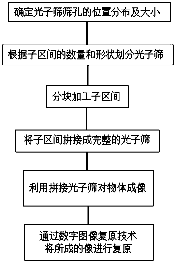
[0036] A manufacturing method of splicing large aperture photonic sieve, such as figure 1 shown, including the following steps:

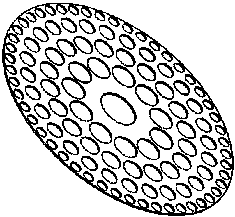
[0037] The first step is to design a large aperture photonic sieve, image 3 Shown is a complete schematic diagram of the photon sieve structure, with a diameter of D, where the position distribution of the photon sieve light holes satisfies the equation:

[0038]

[0039] In the formula, f is the focal length of the photon sieve, n is the ring band number of the optical ring, λ is the working wavelength of the photon sieve, R is the radius of the photon sieve, α is the cubic coding coefficient, k is the wave number, x m and y m is the center position of the mth pinhole on the nth pass ring. The aperture diameter d of the photon sieve is set as a multiple of the bright ring band width of the Fresnel zone plate. where the width of the bright ring band of the Fresnel zone plate

[0040] In this embodiment, the third-order coding coefficient...


PUM


Abstract

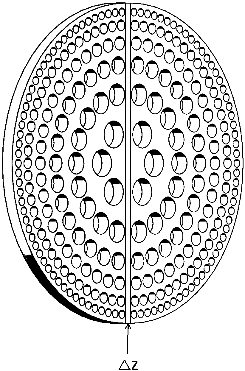
The invention belongs to the optical field, solves a technical problem of reduction of the resolution of a photon sieve after splicing due to a large-caliber photon screen splicing error and disclosesa method for manufacturing a spliced large-caliber photon sieve. The method comprises steps that position distribution of photon sieve holes and the size of the sieve holes are determined according to parameters such as the caliber of the photon sieve and the working wavelength, and position distribution of the photon sieve holes is phase-encoded; the designed large-caliber photon sieve is divided into several sub-intervals; each sub-interval is processed separately; the sub-intervals are spliced into a complete photon sieve; the digital image restoration technology is utilized to restore anobject through images formed by the photon sieve. The method is advantaged in that the large-sized photon sieve can be manufactured, the wavefront coding technology is utilized to reduce adjustment accuracy of the photon sieve during splicing, and imaging quality of the completed spliced photon sieve is further guaranteed.

Description

technical field [0001] The invention belongs to the field of optics, and in particular relates to a photonic sieve, in particular to a manufacturing method of a large-area spliced ​​photonic sieve. Background technique [0002] Photon sieve is a new type of diffractive optical element proposed by Kipp in 2001, which has diffractive optical properties similar to Fresnel zone plates. The photon sieve, like the Fresnel zone plate, transmits light to the odd or even Fresnel band, while making the adjacent bands opaque. The photonic sieve designs the light-transmitting wavelength band into light-transmitting micropores. These micropores are located on the wavelength band. The difference between the distance of the light wave passing through the center of each micropore to the focus and the distance reaching the focus through the optical axis is an integer multiple of the wavelength. So focusing and imaging can be achieved. Photonic sieves have the characteristics of light weigh...

Claims


Application Information

Patent Timeline
Patent Type & Authority Applications(China)
IPC IPC(8): G02B5/18
CPCG02B5/1847G02B5/1876
Inventor 许峰郑鹏磊胡正文王钦华
Owner SUZHOU UNIV
Learn More