100% low floor trolley car battery assembly
A technology for trams and batteries, applied in the field of rail transit, can solve the problems of tight roof equipment layout space and limited space under the car, and achieve the effects of easy replacement, enhanced safety, and high energy density.
- Summary
- Abstract
- Description
- Claims
- Application Information
AI Technical Summary
Problems solved by technology
Method used
Image

Examples
Embodiment
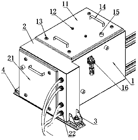
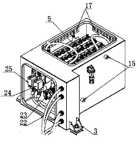
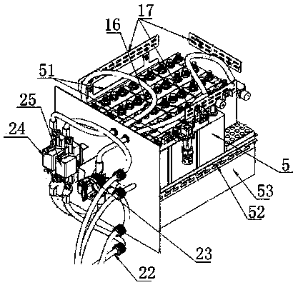
[0049] Such as figure 1 , 2 , 3, and 4, a 100% low-floor tram battery assembly, including a battery pack box 1 and an isolation protection device box 2 connected as one. The top of the battery box 1 is provided with a battery box door 11 with a door handle 14, inside the battery box 5 is placed a number of battery cells in series, and the battery box 5 is surrounded by partitions 53 and placed in the battery box. The inner side wall of the box body 1 is provided with a top surface fixing bracket 51 and a side surface fixing bracket 52, and the top surface fixing bracket 51 directly presses on the top of the battery pack 1 to fix the vertical position of the battery pack 5; The horizontal position of 5 is fixed. An isolation protection box door 21 with a door handle 14 is arranged on the side of the isolation protection device box body 2 .
[0050] After the positive and negative cables 22 of the battery pack 5 enter the isolation protection device box 2, a fuse-24 and a man...
PUM
 Abstract
Description
Claims
Application Information
 - R&D
- Intellectual Property
- Life Sciences
- Materials
- Tech Scout
- Unparalleled Data Quality
- Higher Quality Content
- 60% Fewer Hallucinations
Browse by: Latest US Patents, China's latest patents, Technical Efficacy Thesaurus, Application Domain, Technology Topic, Popular Technical Reports.
© 2025 PatSnap. All rights reserved.Legal|Privacy policy|Modern Slavery Act Transparency Statement|Sitemap|About US| Contact US: help@patsnap.com