

Cervical traction device
A cervical vertebra traction and neck brace technology, applied in the field of medical devices, can solve problems such as head angle changes, affecting traction effects, etc., to increase oxygen content, avoid angle changes, and increase health care effects.
Inactive Publication Date: 2018-11-09
余庆县中医医院
View PDF0 Cites 5 Cited by
- Summary
- Abstract
- Description
- Claims
- Application Information
AI Technical Summary
Problems solved by technology
[0004] The present invention intends to provide a cervical spine migration device to solve the technical problem that the cervical spine traction treatment device in the prior art tends to change the head angle due to the traction force during the traction process, thereby affecting the traction effect
Method used
View moreImage
Smart ImageViewing Examples

Examples
Embodiment Construction
[0015] Further detailed explanation through specific implementation mode below:
Login to View More PUM
 Abstract
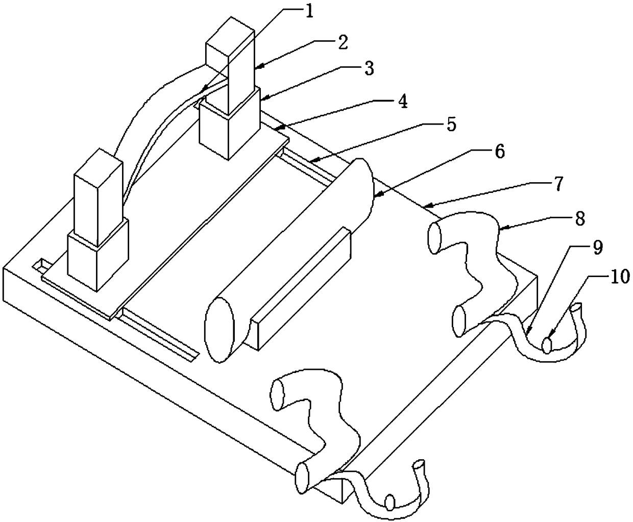
The invention discloses a cervical traction device in the field of medical apparatuses and instruments. The cervical traction device comprises a base, wherein a head positioning mechanism, a neck supporting pillow and shoulder constraint straps are sequentially connected on the base in one direction. The head positioning mechanism comprises two extensible arms respectively connected to two opposite sides of the base, and a tensioning belt with an upwards arched middle is connected between the extensible arms. The number of the shoulder constraint straps is two, the two shoulder constraint straps are respectively located on two opposite sides of the base, one end of each shoulder constraint strap is fixedly connected with the base, and the other end of each shoulder constraint strap is detachably connected with the base. When the cervical traction device is used for correcting the cervical vertebra, generally, body discomfort is caused and further spontaneous shaking is very likely to occur due to the fact that the body position in a corrected state is different from an ordinary non-normal position. By adopting the scheme, the spontaneously shaking head and shoulders at two ends ofthe neck are fixed, angle change of the head and shoulders is avoided, and the smooth cervical vertebra correcting process is ensured.
Description
technical field [0001] The invention relates to the field of medical equipment, in particular to a cervical traction device. Background technique [0002] Cervical traction is the main means of relieving symptoms in the treatment of cervical spondylosis. Because effective traction can relieve the compression of nerves, blood vessels, and spinal cord, and quickly relieve the symptoms of cervical spondylosis. Specifically speaking, cervical traction is mainly to relieve neck muscle spasm, relieve pain symptoms, increase intervertebral space and intervertebral foramen, facilitate the restoration of protruding nucleus pulposus and annulus fibrosus, relieve and relieve nerve root compression and stimulation, Promote the absorption of nerve root edema, relieve the compression on the vertebral artery, promote blood circulation, help local congestion, swelling and hyperplasia subside, loosen the joint capsule, improve and restore the hook vertebral joint, adjust the misalignment of...
Claims
Login to View More Application Information
Patent Timeline
 Patent Type & AuthorityApplications(China)
IPC IPC(8): A61F5/042A61N2/08A61F7/00
CPCA61F5/042A61F7/007A61F2007/0011A61F2007/0071A61N2/002A61N2/008A61N2/06
Inventor陈普庆周潋余通汉
Owner余庆县中医医院