A small photovoltaic power generation device that automatically follows the sun

A photovoltaic power generation and automatic follow-up technology, applied in the field of solar energy utilization, can solve the problems of large volume of photovoltaic devices, inability to choose installation, low conversion rate, etc., to improve the aesthetics, avoid excessive heating, and small footprint.

Active Publication Date: 2021-11-23
东营金丰正阳科技发展有限公司
View PDF0 Cites 1 Cited by
  • Summary
  • Abstract
  • Description
  • Claims
  • Application Information

AI Technical Summary

Problems solved by technology

[0003] However, most of the photovoltaic devices currently used are large in size, and large-scale photovoltaic power generation systems are usually installed in open areas in a matrix form. Since the irradiation of light will change direction with the rotation of the earth, photovoltaic power generation devices have a high impact on geographical location. Some small household photovoltaic power generation devices cannot choose the best location for installation, and the conversion rate is low due to changes in the direction of sunlight during use, so there are disadvantages in use

Method used


Image

  • A small photovoltaic power generation device that automatically follows the sun
  • A small photovoltaic power generation device that automatically follows the sun
  • A small photovoltaic power generation device that automatically follows the sun

Examples


Embodiment 1

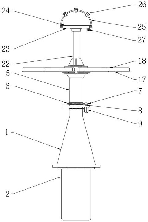
[0032] A small photovoltaic power generation device that automatically follows sunlight, comprising a base 1, a first extension tube 5 and a second extension tube 22, the diameter of the base 1 decreases from bottom to top, and a bottom case 2 is installed on the bottom of the base 1, while The central axis of the bottom case 2 and the central axis of the base 1 are on the same vertical line, and the base 1, the first extension tube 5 and the second extension tube 22 are all hollow structures, which facilitate the wiring of the device inside;

[0033]The first extension tube 5 is installed on the top of the base 1, and the central axis of the first extension tube 5 is on the same vertical line as the central axis of the base 1, and the distance between the upper part and the lower part of the first extension tube 5 is The connection method is a rotary connection, wherein the lower part of the first extension tube 5 is a circular tube structure, and the upper part of the first e...

Embodiment 2

[0036] The features of this embodiment that are the same as those of Embodiment 1 will not be repeated here. The difference between this embodiment and Embodiment 1 is that in this embodiment, the base 1 includes a battery 3 and a main control module 4; the battery 3 is installed in Inside the bottom case 2, and the top of the battery 3 extends to the inside of the base 1; the main control module 4 is installed on the upper end inside the base 1, and the main control module 4 is electrically connected to the battery 3, and the bottom case 2 is wrapped on the outside of the battery 3, Moreover, the bottom case 2 is buried under the ground during use, which effectively avoids the radiant heat of the sun, improves the heat dissipation rate of the battery 3 as a whole, and ensures that the low temperature state is maintained during the working process.

Embodiment 3

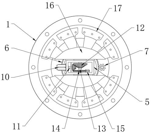
[0038] The features of this embodiment that are the same as those of Embodiment 1 will not be repeated. The difference between this embodiment and Embodiment 1 is that, in this embodiment, the first extension tube 5 includes a transmission disc 6, a first servo motor 9, a first Two servo motors 10 and chucks 14, the drive disc 6 is installed on the lower outer wall of the first extension tube 5, and the drive disc 6 is meshed with a driving wheel 7; the first servo motor 9 is installed on the first extension tube 5, and the top of the first servo motor shaft 8 forms a rotating structure through the first servo motor shaft 8 and the driving wheel 7; the second servo motor 10 is installed on the upper side of the first extension tube 5, and One end of the second servo motor 10 is rotatably connected with a second servo motor shaft 11; the second servo motor shaft 11 runs through the outer wall of the first extension tube 5 to cooperate with the bevel gear set 12 and the main shaf...


PUM


Abstract

The invention discloses a small photovoltaic power generation device that automatically follows sunlight, which comprises a base, a first extension tube and a second extension tube, the diameter of the base decreases from bottom to top, and a bottom case is installed on the bottom of the base, and the bottom case The central axis of the base and the central axis of the base are on the same vertical line. The overall structure of the device is compact, in the form of a lamppost structure, with a small footprint and is suitable for various occasions. There are eight blade-type photovoltaic panels on the top. The umbrella-shaped structure is formed as a whole, which improves the overall aesthetics of the device. At the same time, the battery is buried under the ground with the bottom case, which can effectively prevent the sun from causing the battery to heat up too quickly, and the ground wrapping outside the bottom case can improve the overall heat dissipation efficiency and improve Use security.

Description

technical field [0001] The invention relates to the technical field related to solar energy utilization, in particular to a small photovoltaic power generation device that automatically follows sunlight. Background technique [0002] Solar energy is a kind of renewable energy. It refers to the thermal radiation energy of the sun. There are two types of photoelectric conversion. Solar power generation is a new type of renewable energy, and solar power generation requires the use of photovoltaic panel components. It is a power generation device that generates direct current when exposed to sunlight, and is almost entirely made of semiconductor materials. Composition of solid photovoltaic cells. [0003] However, most of the photovoltaic devices currently in use are large in size, and large-scale photovoltaic power generation systems are usually installed in an open area in a matrix form. Since the irradiation of light will change direction with the rotation of the earth, phot...

Claims


Application Information

Patent Timeline
Patent Type & Authority Patents(China)
IPC IPC(8): H02S20/32H02S40/30F24S50/20F24S30/45
CPCF24S30/45F24S50/20H02S20/32H02S40/30Y02E10/47Y02E10/50
Inventor 安世凯
Owner 东营金丰正阳科技发展有限公司
Why Eureka
Try Eureka