Ultrasonic cleaning tank convenient for cleaning solution replacement

A technology of cleaning tank and cleaning liquid

Inactive Publication Date: 2018-11-09
SUZHOU LIN XINYUAN AUTOMATION TECH CO LTD
View PDF9 Cites 0 Cited by
  • Summary
  • Abstract
  • Description
  • Claims
  • Application Information

AI Technical Summary

Problems solved by technology

The principle of the ultrasonic cleaner is that the high-frequency oscillation signal sent by the ultrasonic generator is converted into high-frequency mechanical oscillation by the transducer and propagated into the medium-cleaning liquid. , make the liquid flow and generate tens of thousands of tiny bubbles, these bubbles form and grow in the negative pressure zone where the ultrasonic wave propagates longitudinally, and quickly close in the positive pressure zone, in this process called "cavitation" effect The closed air bubbles in the middle may form an instantaneous high pressure of more than 1000 air pressures, and the continuous high pressure is like a series of small "explosions" that continuously impact the surface of the object, so that the dirt on the surface and gaps of the object will be peeled off quickly, so as to achieve a comprehensive and clean cleaning of the object effect, but in the current ultrasonic cleaning equipment, many ultrasonic cleaning tanks are difficult to easily replace the cleaning solution due to structural reasons, and the ultrasonic cleaning tank will produce a lot of impurities during use, and the internal cleaning tank It is difficult to clean when the cleaning fluid is replaced, so we propose an ultrasonic cleaning tank that is easy to replace the cleaning fluid to solve the above problems

Method used


Image

  • Ultrasonic cleaning tank convenient for cleaning solution replacement
  • Ultrasonic cleaning tank convenient for cleaning solution replacement
  • Ultrasonic cleaning tank convenient for cleaning solution replacement

Examples


Embodiment Construction

[0014] The following will clearly and completely describe the technical solutions in the embodiments of the present invention with reference to the accompanying drawings in the embodiments of the present invention. Obviously, the described embodiments are only some, not all, embodiments of the present invention. Based on the embodiments of the present invention, all other embodiments obtained by persons of ordinary skill in the art without making creative efforts belong to the protection scope of the present invention.

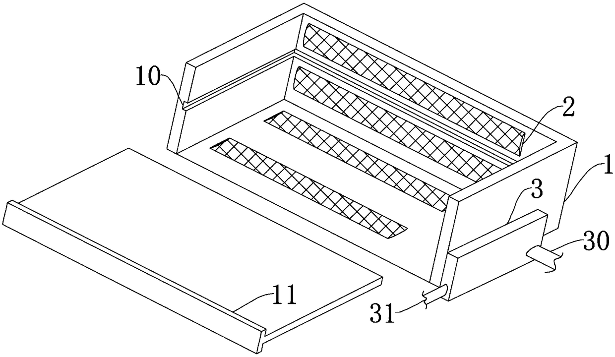
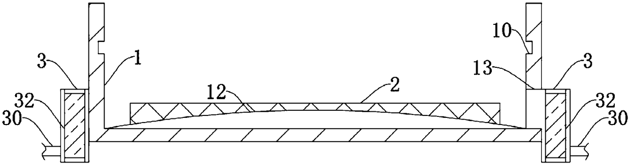
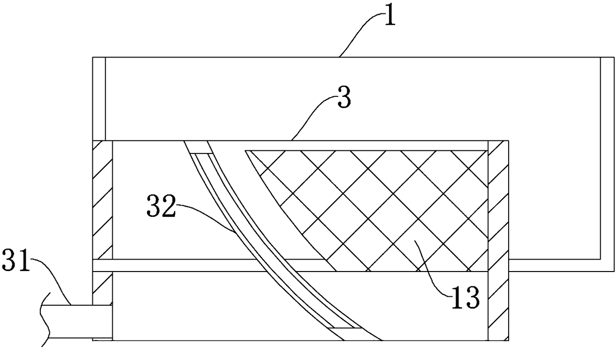
[0015] see Figure 1-3 , the present invention provides a technical solution: an ultrasonic cleaning tank for easy replacement of cleaning liquid, including a cleaning tank 1, an ultrasonic generator 2 and a cleaning liquid concentration tank 3, the cleaning tank 1 is in the shape of a cavity frame with an upward opening, the The ultrasonic generator 2 is fixed on the inner walls of the front and rear fixed plates and the lower fixed plate of the cleaning tank...


PUM


Abstract

The invention discloses an ultrasonic cleaning tank convenient for cleaning solution replacement. The ultrasonic cleaning tank includes a cleaning tank, an ultrasonic generator and a cleaning solutionconcentrating box. Through the arrangement of a sealing rubber ring on the contact surface of a pulling baffle plate and an embedded groove, the ultrasonic cleaning tank can perform pouring in and flowing out of a cleaning solution under the condition of protecting the sealing performance; through the mutual staggered arrangement of a dredging block and the ultrasonic generator, the dredging block being in an arc shape and integrally cast with the cleaning tank, the height of the dredging block being less than that of the ultrasonic generator, when the ultrasonic cleaning tank is used, impurities can flow better when the cleaning solution flows out; and the length and width of the outlet of the cleaning solution are less than the arc length of filtering baffle plates, the sides of the filtering baffle plates facing to a first water outlet are provided with a filter cotton layer, and the end facing to a second water outlet is provided with a filtering grilling and a spongy layer, so that separation can be better performed on the impurities in the cleaning solution, and the ultrasonic cleaning tank is suitable to actual circumstances.

Description

technical field [0001] The invention relates to the related technical field of ultrasonic cleaning equipment, in particular to an ultrasonic cleaning tank for easy replacement of cleaning liquid. Background technique [0002] Ultrasonic cleaning belongs to the force cleaning in the physical field. It is green cleaning itself. If an appropriate cleaning agent is added to the cleaning solution, it is a combined cleaning, which has a more obvious cleaning effect. Ultrasonic cleaning is more effective in various chemical, physical and mechanical cleaning. It is widely used in industrial sectors such as machinery, optics, electronics, light industry, textile, chemical industry, aerospace, shipbuilding, atomic energy and medical medicine. . The principle of the ultrasonic cleaner is that the high-frequency oscillation signal sent by the ultrasonic generator is converted into high-frequency mechanical oscillation by the transducer and propagated into the medium-cleaning liquid. ,...

Claims


Application Information

Patent Timeline
Patent Type & Authority Applications(China)
IPC IPC(8): B08B3/12B08B3/14
CPCB08B3/12B08B3/14
Inventor 刘锡久
Owner SUZHOU LIN XINYUAN AUTOMATION TECH CO LTD
Why Eureka
Try Eureka