Permanent magnet brushless motor Hall position sensor fault diagnosis method

A permanent magnet brushless motor and sensor fault technology, applied in the direction of electric/magnetic position measurement, using electric devices, electromagnetic measuring devices, etc., can solve the problems of poor practicability, achieve good practicability, improve reliability, and ensure reliable operation Effect

Inactive Publication Date: 2018-11-09
NORTHWESTERN POLYTECHNICAL UNIV
View PDF15 Cites 0 Cited by
  • Summary
  • Abstract
  • Description
  • Claims
  • Application Information

AI Technical Summary

Problems solved by technology

[0007] In order to overcome the shortcomings of the poor practicability of the existing fault diagnosis methods, th

Method used


Image

  • Permanent magnet brushless motor Hall position sensor fault diagnosis method
  • Permanent magnet brushless motor Hall position sensor fault diagnosis method
  • Permanent magnet brushless motor Hall position sensor fault diagnosis method

Examples


Example Embodiment

[0025] The following examples refer to Figure 1-4 .

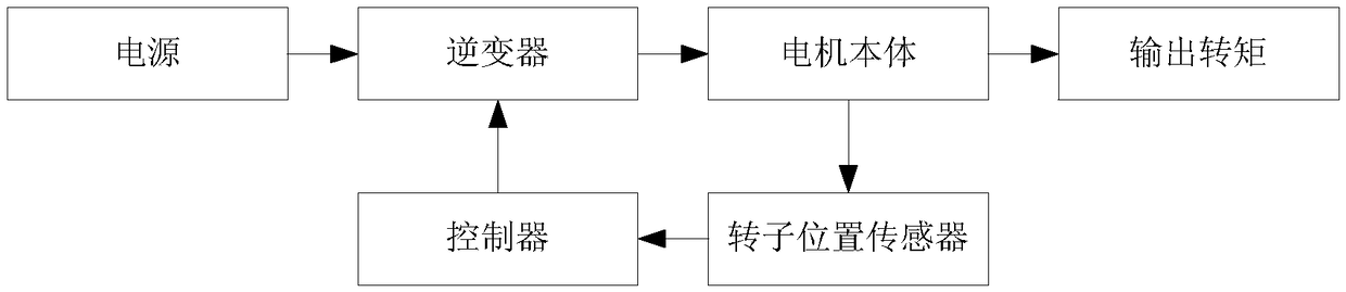
[0026] In this embodiment, TMS320F2812 of Texas Instruments is used as the control chip, IR2136 is used as the driving chip, and a three-phase bridge circuit is selected to drive the permanent magnet brushless motor.

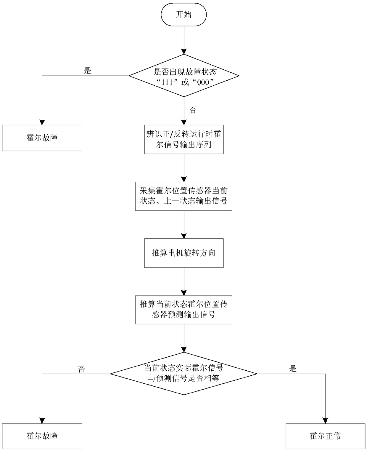
[0027] The specific steps of the fault diagnosis method of the permanent magnet brushless motor Hall position sensor of the present invention are as follows:
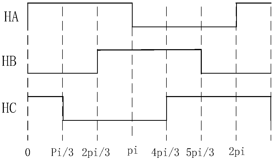
[0028] Step 1: When the permanent magnet brushless motor is running, the three-way Hall position sensor can output up to eight states of "000, 001, 010, 011, 100, 101, 110, 111", among which "000, 111" is Failure status. A one-dimensional array Hall with a length of 8 is used to represent these eight states respectively, among which Hall[0] and Hall[7] are fault states. The system judges whether the Hall position sensor is present by detecting whether the Hall sensor has a fault state. malfunction. If the Hall position sensor has a "111" fault, then Faul...


PUM


Abstract

The invention discloses a permanent magnet brushless motor Hall position sensor fault diagnosis method, which is used for solving the technical problem of poor practicability of the existing fault diagnosis method. According to the technical scheme, firstly, the output sequence of three paths of Hall position sensors during the positive and reverse operation of the permanent magnet brushless motoris recognized; then, the current position signals of a permanent magnet brushless motor rotor output by the Hall position sensors, the former position signals of the permanent magnet brushless motorrotor output by the Hall position sensors, and the predicted current position signals and the permanent magnet brushless motor rotating direction of the permanent magnet brushless motor rotor output by the Hall position sensors are collected; meanwhile, whether the output signals are identical or not is predicted according to the current output signals of the Hall position []sensors and the predicated output signals of the Hall position sensor, so that the Hall position sensor fault problem of the permanent magnet brushless motor under the operation work conditions of low rotating speed and frequent positive and reverse rotation is detected; the reliable operation of an airplane full electric braking system is ensured; the practicability is high.

Description

technical field [0001] The invention relates to a fault diagnosis method, in particular to a fault diagnosis method for a hall position sensor of a permanent magnet brushless motor. Background technique [0002] The permanent magnet brushless motor is an AC motor with a permanent magnet rotor. It has the advantages of simple structure, high power density and high efficiency. It is widely used in aerospace, CNC machine tools and other mechatronics fields. The permanent magnet brushless motor generally adopts two-two conduction control mode, and needs to obtain six rotor position signals for electronic commutation in one electrical cycle. At present, the installation method of 60° interval or 120° interval is often used, and three Hall position sensors are installed for motor rotor position detection. However, the harsh environment, severe vibration, connecting wires and other conditions will cause the Hall position sensor to fail. If the Hall position sensor of a certain ph...

Claims


Application Information

Patent Timeline
IPC IPC(8): G01B7/00
CPCG01B7/003G01B21/042
Inventor 林辉赵逸云齐蓉李兵强张希王君
Owner NORTHWESTERN POLYTECHNICAL UNIV
Why Eureka
Try Eureka