Connection method of upper and lower coordinate systems in deep mining wells based on pseudolites and inertial information

A technology of deep mining and connection method, which is applied in satellite radio beacon positioning system, radio wave measurement system, navigation and other directions, can solve the problem of occupying the wellbore for a long time, increasing the ranging error of the photoelectric range finder, and the degree of stability. Advanced problems, to achieve the effect of saving manpower and high precision

Active Publication Date: 2022-05-17
CHINA UNIV OF MINING & TECH
View PDF4 Cites 0 Cited by
  • Summary
  • Abstract
  • Description
  • Claims
  • Application Information

AI Technical Summary

Problems solved by technology

[0004] The traditional method has higher requirements on the measurement environment. The connecting triangle method requires simultaneous measurement up and down the well to ensure accuracy, and takes a long time in the wellbore; the gyroscope azimuth method has higher requirements on the environment, and each measurement takes a long time. The mining activities near the wellbore must be stopped, the instruments are expensive, and the measurement accuracy is highly related to the stability of the steel wire. For deep mining, the stability of the steel wire is limited; the elevation contact measurement faces the same situation. The environment poses challenges to the measurement of long steel rulers, long steel wires, and photoelectric distance meters. The stretching and verticality of steel rulers and steel wires are related to temperature and materials. Factors such as dust and water vapor in the wellbore will increase photoelectric distance measurement. ranging error

Method used


Image

  • Connection method of upper and lower coordinate systems in deep mining wells based on pseudolites and inertial information
  • Connection method of upper and lower coordinate systems in deep mining wells based on pseudolites and inertial information

Examples


specific Embodiment approach

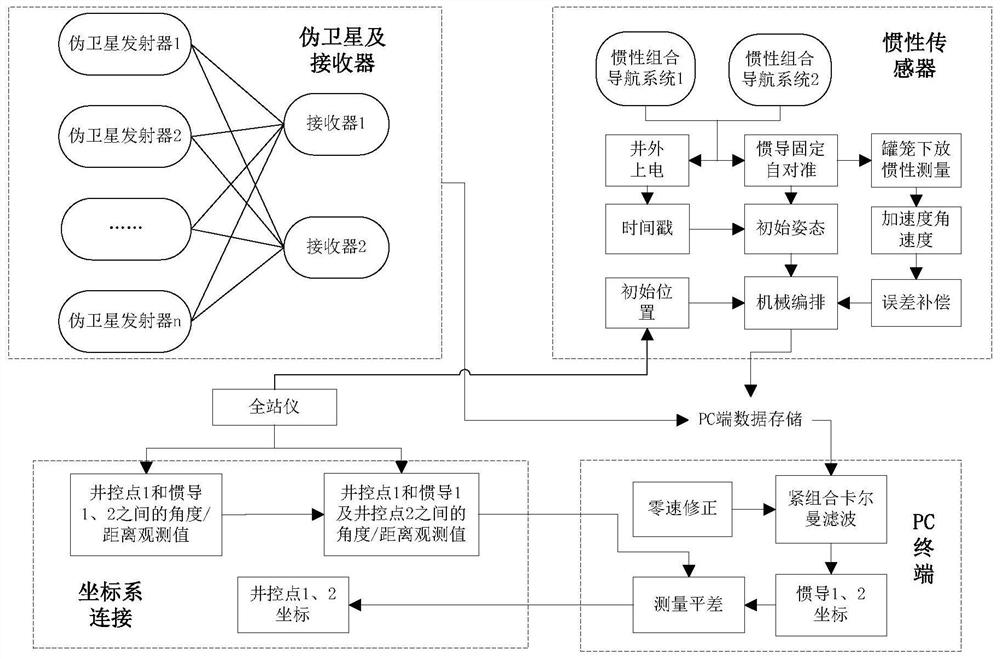
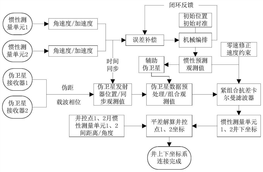
[0030] a. Firstly, according to the mine cross-section diagram, arrange multiple pseudolite transmitters on the characteristic points in different directions on the upper part of the shaft, and use the total station to accurately determine the coordinates of the pseudolite.

[0031] b, lift the cage, fix two inertial measurement systems on the two ends of the cage top; at the same time, fix the pseudolite receiver on the top and bottom of the cage; use a total station to accurately measure the lever arm value respectively, wherein the lever arm value is The difference between the center of the pseudolite receiver relative to the center of the inertial measurement unit in the three axes.

[0032] c. Put the cage down, perform inertial measurement and pseudolite measurement, use the PC terminal to store the inertial data and satellite data, and finally synchronize the data and clock.

[0033] d. When the cage reaches the bottom of the wellbore, use a total station to measure the...


PUM


Abstract

The invention discloses a method for connecting the upper and lower coordinate systems of deep mining shafts based on pseudolite and inertial information. In the method, a plurality of pseudolite transmitters are arranged on characteristic points in different directions on the upper part of the shaft according to the section diagram of the mine, and a total station is used to Determine the coordinates of the pseudolite launcher; fix the inertial measurement system on both ends of the top of the cage respectively, use the total station to measure the initial coordinates of the inertial measurement unit, and use the total station to accurately measure the lever arm value relative to the center of the inertial measurement unit Obtain the pseudo-range and carrier phase observation values ​​through the pseudo-satellite transmitter arranged on the inner wall of the wellbore, use the inertial measurement unit to obtain angular velocity and acceleration information, and use the PC terminal to perform compact combination data calculation on the stored inertial data and pseudo-satellite data, The invention can use the cage device to obtain observation values ​​quickly and with high precision, overcome the disadvantages of the traditional method being restricted by temperature, humidity and construction, save manpower and material resources, and ensure production.

Description

technical field [0001] The invention relates to a method for connecting the upper and lower coordinate systems of a well, in particular to a method for connecting the upper and lower coordinate systems of a deep mining well based on pseudolites and inertial information. Background technique [0002] For deep precision mining, spatial reference can provide an important basis for underground mining operation, safety early warning and disaster decision-making. The mine spatial benchmark requires that the upper and lower coordinate systems of the mine be consistent, and the above-ground coordinate system is introduced into the underground, that is, contact measurement. However, for deep shafts, the depth of the mine is relatively large, and the temperature, light, humidity and other factors in the mine bring difficulties to the connection measurement, and the measurement accuracy is limited. [0003] Traditional contact measurement is mainly divided into plane contact measureme...

Claims


Application Information

Patent Timeline
Patent Type & Authority Patents(China)
IPC IPC(8): G01C21/00G01C21/16G01S19/49G01D21/02
CPCG01C21/005G01C21/165G01D21/02G01S19/49
Inventor 李增科赵龙王一帆
Owner CHINA UNIV OF MINING & TECH
Why Eureka
Try Eureka