Optical module

A technology of optical modules and optical fiber ribbons, applied in the field of optical modules, can solve problems such as low optical coupling efficiency

Inactive Publication Date: 2018-11-09
HISENSE BROADBAND MULTIMEDIA TECH
View PDF2 Cites 10 Cited by
  • Summary
  • Abstract
  • Description
  • Claims
  • Application Information

AI Technical Summary

Problems solved by technology

[0004] An embodiment of the present invention provides an optical module to solve the problem of low optical coupling efficiency of existing optical modules

Method used


Image

  • Optical module
  • Optical module
  • Optical module

Examples


Embodiment Construction

[0047] In order to make the purpose, technical solutions and advantages of the embodiments of the present invention clearer, the technical solutions in the embodiments of the present invention will be clearly and completely described below in conjunction with the drawings in the embodiments of the present invention. Obviously, the described embodiments It is a part of embodiments of the present invention, but not all embodiments. Based on the embodiments of the present invention, all other embodiments obtained by persons of ordinary skill in the art without creative efforts fall within the protection scope of the present invention.

[0048] The optical module described in this embodiment is a transceiver integrated optical module with a receiving function and a transmitting function.

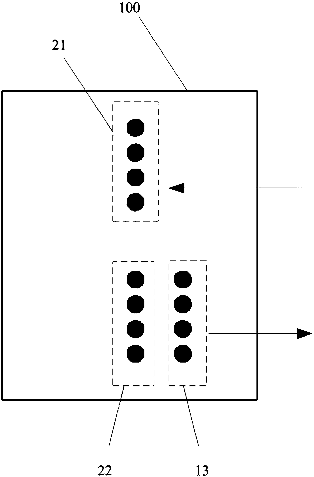
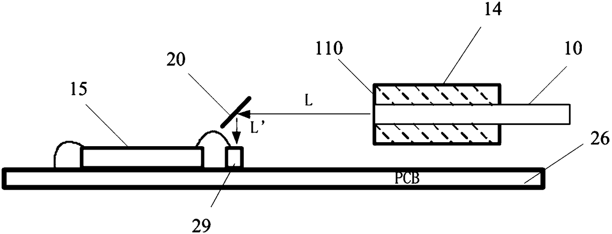
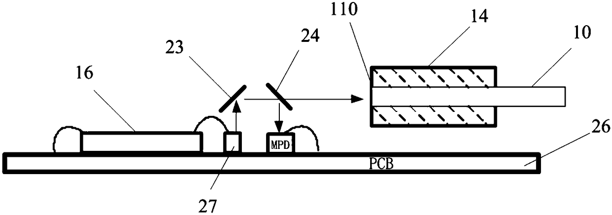
[0049] figure 1 It is a schematic diagram of the distribution of the lenses on the lens assembly in the existing optical module, figure 2 is a schematic structural diagram of the receiving en...


PUM


Abstract

The embodiment of the invention provides an optical module. The optical module comprises a PCB, an optical receiver, a laser, a lens assembly and an optical fiber ribbon, wherein the optical receiver,the laser, the lens assembly and the optical fiber ribbon are arranged on the PCB; the lens assembly comprises a light-transmitting body; a first collimating lens, a first reflector and a first condensing lens are sequentially arranged on the body in the direction of a receiving optical path; a second collimating lens, a second reflector, a filter sheet and a second condensing lens are sequentially arranged on the body in the direction of an emitting light path; the first condensing lens is arranged above the optical receiver; and the second collimating lens is arranged above the laser. According to the optical module, the horizontal distance between the first reflector and the optical fiber end surface of the optical fiber ribbon is smaller than the horizontal distance between the secondreflector and the optical fiber end surface of the optical fiber ribbon, then the vertical distance between the first condensing lens and an optical fiber ribbon connector is increased, so that the optical fiber ribbon connector with the standard thickness is used, and therefore the manufacturing cost of the optical fiber ribbon joint is lowered, and the connecting reliability of the optical fiber ribbon connector and the lens assembly is improved.

Description

technical field [0001] Embodiments of the present invention relate to optoelectronic communication technologies, and in particular to an optical module. Background technique [0002] The parallel optical module is mainly based on the optical interconnection technology of multi-mode optical fiber, which has the advantages of high bandwidth, low loss, no crosstalk, matching and electromagnetic compatibility issues, and has gradually replaced the electrical interconnection products based on copper wires and is used in cabinets and racks. The high-speed interconnection between them, the connection distance is up to 300 meters under OM3 optical fiber. [0003] The parallel optical module is connected to the optical fiber through the optical fiber ribbon connector. However, the existing parallel optical module with the function of transmitting and receiving includes the components of the receiving optical module and the components of the transmitting optical module, and the number...

Claims


Application Information

Patent Timeline
Patent Type & Authority Applications(China)
IPC IPC(8): G02B6/42
CPCG02B6/4214
Inventor 贲仕建刘旭霞
Owner HISENSE BROADBAND MULTIMEDIA TECH
Why Eureka
Try Eureka