A Microstrip Antenna with Filtering Characteristics and Its Design Method

A technology of microstrip antenna and filtering characteristics, applied in waveguide devices, resonators, electrical components, etc., can solve the problems of increasing system complexity, increasing weight, size and loss, poor versatility, etc., and achieve good out-of-band suppression characteristics , flat gain, and well-integrated effects

Active Publication Date: 2020-01-31
CHINA SHIP DEV & DESIGN CENT
View PDF9 Cites 0 Cited by
  • Summary
  • Abstract
  • Description
  • Claims
  • Application Information

AI Technical Summary

Problems solved by technology

The first technique is to use the coupling effect between multiple radiators to obtain the filtering characteristics of the antenna. For example, the microstrip patch antenna uses four layers of patches to couple each other to generate resonance, and a microstrip antenna with filtering characteristics is obtained, but this This design method is highly dependent on the designer's engineering experience, it is not suitable for expansion and promotion, and its versatility is relatively poor
The second technique is to introduce an additional transformation structure to obtain the filtering characteristics of the antenna. For example, an additional impedance transformation structure is designed between the filter and the antenna to obtain better impedance bandwidth and filtering characteristics. However, this transformation structure increases increases the complexity of the overall system, including increasing its weight, size and losses

Method used


Image

  • A Microstrip Antenna with Filtering Characteristics and Its Design Method
  • A Microstrip Antenna with Filtering Characteristics and Its Design Method
  • A Microstrip Antenna with Filtering Characteristics and Its Design Method

Examples


Embodiment Construction

[0028] The present invention will be further described in detail below in conjunction with the accompanying drawings and embodiments.

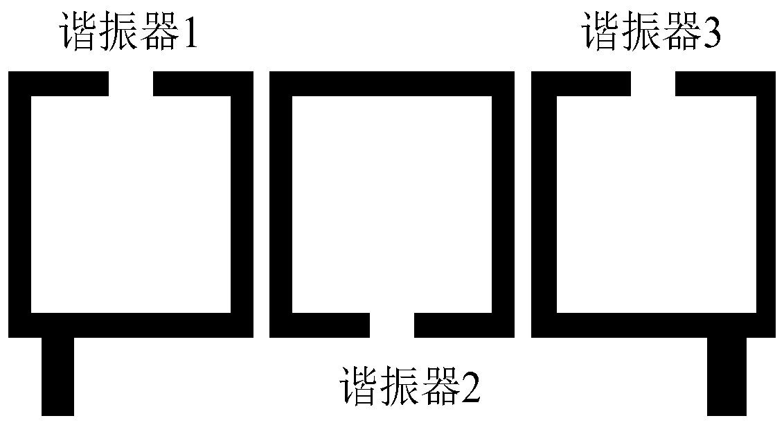
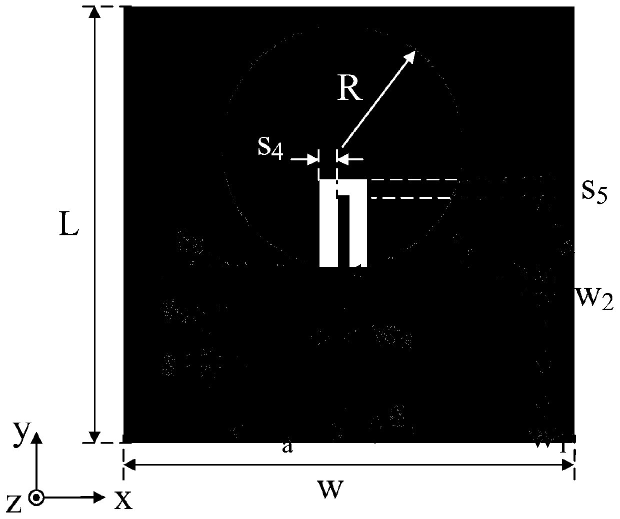
[0029] The geometric structure of the microstrip antenna with filter characteristics of the present invention is as attached figure 2 As shown, it consists of a circular microstrip antenna, a T-shaped resonator and a microstrip rectangular split-ring resonator. When designing a circular microstrip antenna with filtering characteristics, it is first necessary to comprehensively design a third-order Chebyshev-coupled bandpass filter, including three rectangular split-ring resonators, as shown in the attached figure 1 shown. A third-order Chebyshev coupled bandpass filter with 0.1dB equiripple, center frequency of 2.45GHz and impedance bandwidth of 10% is designed by using the coupling bandpass filter synthesis method. The coupling coefficient between the three rectangular split ring resonators is k 12 =k 23 =0.092, where k 12 is the coupli...


PUM


Abstract

The present invention provides a microstrip antenna with a filtering feature and a design method thereof. The microstrip antenna comprises a circular microstrip antenna, a T-shaped resonator and a microstrip rectangular snap ring resonator, the circular microstrip antenna is provided with a rectangular notch, a vertical arm, distributed along a y shaft, of the T-shaped resonator is inserted into the rectangular notch of the circular microstrip antenna, and a horizontal arm, distributed along an x shaft, of the T-shaped resonator is arranged close to the microstrip rectangular snap ring resonator. The design method comprises the steps of: designing resonant frequency meeting the three-order Chebyshev coupling band-pass filter demand, designing a coupling coefficient between the T-shaped resonator and the microstrip rectangular snap ring resonator, and designing that the demand of the filter to the quality factor of the circular microstrip antenna is met. The microstrip antenna is compact in structure, has frequency filter features being similar to a traditional band-pass filter, the antenna gain is flat in the passband, and the radiation feature is good; and moreover, the microstripantenna has a good out-of-band rejection feature out of the frequency band and can effectively isolate the out-of-band interference signals.

Description

technical field [0001] The invention belongs to the field of electromagnetic compatibility and antenna technology, and in particular relates to a microstrip antenna with filtering characteristics and a design method thereof. Background technique [0002] With the rapid development of various wireless communication systems such as modern wireless local area networks and mobile media devices, wireless communication frequency bands are becoming more and more crowded, resulting in the deterioration of wireless communication signal transmission quality and the system is susceptible to interference. In order to deal with such challenges , which puts forward higher requirements on the filtering characteristics of the wireless communication system antenna. In order to ensure that the wireless communication system has the characteristics of high transmission quality, high data transmission rate, and miniaturization, the antenna used as signal radiation and reception is required to ha...

Claims


Application Information

Patent Timeline
Patent Type & Authority Patents(China)
IPC IPC(8): H01Q1/38H01P1/203H01P7/08
CPCH01P1/20381H01P7/082H01Q1/38
Inventor 吴为军刘其凤谭辉陈亮方重华
Owner CHINA SHIP DEV & DESIGN CENT
Why Eureka
Try Eureka